- 您現(xiàn)在的位置:買賣IC網(wǎng) > PDF目錄366550 > AM79C940 (Advanced Micro Devices, Inc.) Media Access Controller for Ethernet (MACE) PDF資料下載
參數(shù)資料
| 型號(hào): | AM79C940 |
| 廠商: | Advanced Micro Devices, Inc. |
| 英文描述: | Media Access Controller for Ethernet (MACE) |
| 中文描述: | 媒體訪問控制器(MACE發(fā)生以太網(wǎng)) |
| 文件頁(yè)數(shù): | 40/122頁(yè) |
| 文件大小: | 914K |
| 代理商: | AM79C940 |
第1頁(yè)第2頁(yè)第3頁(yè)第4頁(yè)第5頁(yè)第6頁(yè)第7頁(yè)第8頁(yè)第9頁(yè)第10頁(yè)第11頁(yè)第12頁(yè)第13頁(yè)第14頁(yè)第15頁(yè)第16頁(yè)第17頁(yè)第18頁(yè)第19頁(yè)第20頁(yè)第21頁(yè)第22頁(yè)第23頁(yè)第24頁(yè)第25頁(yè)第26頁(yè)第27頁(yè)第28頁(yè)第29頁(yè)第30頁(yè)第31頁(yè)第32頁(yè)第33頁(yè)第34頁(yè)第35頁(yè)第36頁(yè)第37頁(yè)第38頁(yè)第39頁(yè)當(dāng)前第40頁(yè)第41頁(yè)第42頁(yè)第43頁(yè)第44頁(yè)第45頁(yè)第46頁(yè)第47頁(yè)第48頁(yè)第49頁(yè)第50頁(yè)第51頁(yè)第52頁(yè)第53頁(yè)第54頁(yè)第55頁(yè)第56頁(yè)第57頁(yè)第58頁(yè)第59頁(yè)第60頁(yè)第61頁(yè)第62頁(yè)第63頁(yè)第64頁(yè)第65頁(yè)第66頁(yè)第67頁(yè)第68頁(yè)第69頁(yè)第70頁(yè)第71頁(yè)第72頁(yè)第73頁(yè)第74頁(yè)第75頁(yè)第76頁(yè)第77頁(yè)第78頁(yè)第79頁(yè)第80頁(yè)第81頁(yè)第82頁(yè)第83頁(yè)第84頁(yè)第85頁(yè)第86頁(yè)第87頁(yè)第88頁(yè)第89頁(yè)第90頁(yè)第91頁(yè)第92頁(yè)第93頁(yè)第94頁(yè)第95頁(yè)第96頁(yè)第97頁(yè)第98頁(yè)第99頁(yè)第100頁(yè)第101頁(yè)第102頁(yè)第103頁(yè)第104頁(yè)第105頁(yè)第106頁(yè)第107頁(yè)第108頁(yè)第109頁(yè)第110頁(yè)第111頁(yè)第112頁(yè)第113頁(yè)第114頁(yè)第115頁(yè)第116頁(yè)第117頁(yè)第118頁(yè)第119頁(yè)第120頁(yè)第121頁(yè)第122頁(yè)
AMD
40
Am79C940
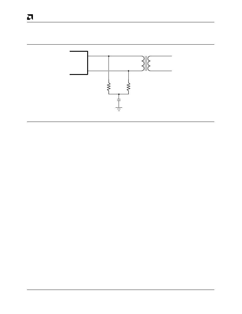
below. The differential input impedance, Z
IDF
, and the
common-mode input impedance, Z
ICM
, are specified so
that the Ethernet specification for cable termination im-
pedance is met using standard 1% resistor terminators.
If SIP devices are used, 39 ohms is also a suitable value.
The CI
±
differential inputs are terminated in exactly the
same way as the DI
±
pair.
MACE
DI+
DI-
40.2
40.2
0.01
μ
F
AUI Isolation
Transformer
16907A-009A
16235C-6
Differential Input Termination
Collision Detection
A transceiver detects the collision condition on the net-
work and generates a differential signal at the CI
±
in-
puts. This collision signal passes through an input stage
which detects signal levels and pulse duration. When
the signal is detected by the MENDEC it sets the CLSN
line HIGH. The condition continues for approximately
1.5 bit times after the last LOW-to-HIGH transition on
CI
±
.
Jitter Tolerance Definition
The Receive Timing-Start of Reception Clock Acquisi-
tion waveform diagram shows the internal timing rela-
tionships implemented for decoding Manchester data in
the SIA module. The SIA utilizes a clock capture circuit
to align its internal data strobe with an incoming bit
stream. The clock acquisition circuitry requires four valid
bits with the values 1010. Clock is phase locked to the
negative transition at the bit cell center of the second “0”
in the pattern.
Since data is strobed at 1/4 bit time, Manchester transi-
tions which shift from their nominal placement through
1/4 bit time will result in improperly decoded data. With
this as the criteria for an error, a definition of “Jitter Han-
dling” is:
The peak deviation approaching or crossing 1/4 bit cell
position from nominal input transition, for which the SIA
section will properly decode data.
Attachment Unit Interface (AUI)
The AUI is the PLS (Physical Signaling) to PMA (Physi-
cal Medium Attachment) interface which effectively con-
nects the DTE to the MAU. The differential interface
provided by the MACE device is fully compliant to Sec-
tion 7 of ISO 8802-3 (ANSI/IEEE 802.3).
After the MACE device initiates a transmission it will ex-
pect to see data looped-backon the DI
±
pair (AUI port
selected). This will internally generate a carrier sense
indicating that the integrity of the data path to and from
the MAU is intact, and that the MAU is operating cor-
rectly. This carrier sensesignal must be asserted during
the transmission when using the AUI port (DO
±
trans-
mitting). If carrier sensedoes not become active in re-
sponse to the data transmission, or becomes inactive
before the end of transmission, the loss of carrier
(LCAR) error bit will be set in the Transmit Frame Status
(bit 7) after the packet has been transmitted.
Digital Attachment Interface (DAI )
The Digital Attachment Interface is a simplified electrical
attachment specification which allows MAUs which do
not require the DC isolation between the MAU and DTE
(e.g. devices compatible with the 10BASE-T Standard
and 10BASE-FL Draft document) to be implemented. All
data transferred across the DAI port is Manchester En-
coded. Decoding and encoding is performed by the
MENDEC.
The DAI port will accept receive data on the basis that
the RXCRS input is active, and will take the data pre-
sented on the RXDAT input as valid Manchester data.
Transmit data is sent to the external transceiver by the
MACE device asserting
TXEN
and presenting compli-
mentary data on the TXDAT
±
pair. During idle, the
MACE device will assert the TXDAT+ line high, and the
TXDAT line low, while
TXEN
is maintained inactive
(high). The MACE device implements logical collision
detection and will use the simultaneous assertion of
TXEN
and RXCRS to internally detect a collision condi-
tion, take appropriate internal action (such as abort the
current transmit or receive activity), and provide exter-
nal indication using the CLSN pin. Any external
相關(guān)PDF資料 |
PDF描述 |
|---|---|
| AM79C940JCW | Media Access Controller for Ethernet (MACE) |
| AM79C940KCW | Media Access Controller for Ethernet (MACE) |
| AM79C960 | PCnetTM-ISA Single-Chip Ethernet Controller |
| AM79C960KC | PCnetTM-ISA Single-Chip Ethernet Controller |
| AM79C960KCW | PCnetTM-ISA Single-Chip Ethernet Controller |
相關(guān)代理商/技術(shù)參數(shù) |
參數(shù)描述 |
|---|---|
| AM79C940_00 | 制造商:AMD 制造商全稱:Advanced Micro Devices 功能描述:Media Access Controller for Ethernet (MACE⑩) |
| AM79C940-16/25 | 制造商:未知廠家 制造商全稱:未知廠家 功能描述: |
| AM79C940-16JC | 制造商:未知廠家 制造商全稱:未知廠家 功能描述:LAN Node Controller |
| AM79C940-25JC | 制造商:未知廠家 制造商全稱:未知廠家 功能描述:LAN Node Controller |
| AM79C940AVC | 制造商:AMD 功能描述:79C940 AMD'94 SMT N6E2A |
發(fā)布緊急采購(gòu),3分鐘左右您將得到回復(fù)。