- 您現(xiàn)在的位置:買賣IC網(wǎng) > PDF目錄376472 > 82C836A-16 (Electronic Theatre Controls, Inc.) Single-Chip 386sx AT PDF資料下載
參數(shù)資料
| 型號(hào): | 82C836A-16 |
| 廠商: | Electronic Theatre Controls, Inc. |
| 英文描述: | Single-Chip 386sx AT |
| 中文描述: | 單芯片386sx在 |
| 文件頁(yè)數(shù): | 66/205頁(yè) |
| 文件大小: | 3878K |
| 代理商: | 82C836A-16 |
第1頁(yè)第2頁(yè)第3頁(yè)第4頁(yè)第5頁(yè)第6頁(yè)第7頁(yè)第8頁(yè)第9頁(yè)第10頁(yè)第11頁(yè)第12頁(yè)第13頁(yè)第14頁(yè)第15頁(yè)第16頁(yè)第17頁(yè)第18頁(yè)第19頁(yè)第20頁(yè)第21頁(yè)第22頁(yè)第23頁(yè)第24頁(yè)第25頁(yè)第26頁(yè)第27頁(yè)第28頁(yè)第29頁(yè)第30頁(yè)第31頁(yè)第32頁(yè)第33頁(yè)第34頁(yè)第35頁(yè)第36頁(yè)第37頁(yè)第38頁(yè)第39頁(yè)第40頁(yè)第41頁(yè)第42頁(yè)第43頁(yè)第44頁(yè)第45頁(yè)第46頁(yè)第47頁(yè)第48頁(yè)第49頁(yè)第50頁(yè)第51頁(yè)第52頁(yè)第53頁(yè)第54頁(yè)第55頁(yè)第56頁(yè)第57頁(yè)第58頁(yè)第59頁(yè)第60頁(yè)第61頁(yè)第62頁(yè)第63頁(yè)第64頁(yè)第65頁(yè)當(dāng)前第66頁(yè)第67頁(yè)第68頁(yè)第69頁(yè)第70頁(yè)第71頁(yè)第72頁(yè)第73頁(yè)第74頁(yè)第75頁(yè)第76頁(yè)第77頁(yè)第78頁(yè)第79頁(yè)第80頁(yè)第81頁(yè)第82頁(yè)第83頁(yè)第84頁(yè)第85頁(yè)第86頁(yè)第87頁(yè)第88頁(yè)第89頁(yè)第90頁(yè)第91頁(yè)第92頁(yè)第93頁(yè)第94頁(yè)第95頁(yè)第96頁(yè)第97頁(yè)第98頁(yè)第99頁(yè)第100頁(yè)第101頁(yè)第102頁(yè)第103頁(yè)第104頁(yè)第105頁(yè)第106頁(yè)第107頁(yè)第108頁(yè)第109頁(yè)第110頁(yè)第111頁(yè)第112頁(yè)第113頁(yè)第114頁(yè)第115頁(yè)第116頁(yè)第117頁(yè)第118頁(yè)第119頁(yè)第120頁(yè)第121頁(yè)第122頁(yè)第123頁(yè)第124頁(yè)第125頁(yè)第126頁(yè)第127頁(yè)第128頁(yè)第129頁(yè)第130頁(yè)第131頁(yè)第132頁(yè)第133頁(yè)第134頁(yè)第135頁(yè)第136頁(yè)第137頁(yè)第138頁(yè)第139頁(yè)第140頁(yè)第141頁(yè)第142頁(yè)第143頁(yè)第144頁(yè)第145頁(yè)第146頁(yè)第147頁(yè)第148頁(yè)第149頁(yè)第150頁(yè)第151頁(yè)第152頁(yè)第153頁(yè)第154頁(yè)第155頁(yè)第156頁(yè)第157頁(yè)第158頁(yè)第159頁(yè)第160頁(yè)第161頁(yè)第162頁(yè)第163頁(yè)第164頁(yè)第165頁(yè)第166頁(yè)第167頁(yè)第168頁(yè)第169頁(yè)第170頁(yè)第171頁(yè)第172頁(yè)第173頁(yè)第174頁(yè)第175頁(yè)第176頁(yè)第177頁(yè)第178頁(yè)第179頁(yè)第180頁(yè)第181頁(yè)第182頁(yè)第183頁(yè)第184頁(yè)第185頁(yè)第186頁(yè)第187頁(yè)第188頁(yè)第189頁(yè)第190頁(yè)第191頁(yè)第192頁(yè)第193頁(yè)第194頁(yè)第195頁(yè)第196頁(yè)第197頁(yè)第198頁(yè)第199頁(yè)第200頁(yè)第201頁(yè)第202頁(yè)第203頁(yè)第204頁(yè)第205頁(yè)

B7
IRQF
The Interrupt Request Flag is set to one when any of the conditions
that can cause an interrupt is true and the interrupt enable for that
condition is true. The condition that causes this bit to be set also
generates an interrupt. The logical expression for this flag is:
IRQF = PF & PIE + AF & AIE + UF & UIE
This bit and all other active bits in this register are cleared by reading
this register or by activation the -PS input pin. Writing to this
register has no effect on the contents.
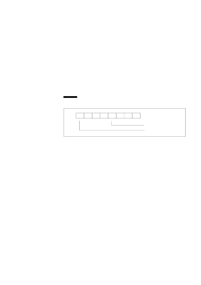
B7
B6
B5
B4
B3
B2
B1
B0
________
________________________________________________________________
0
VRT
Valid RAM and Time
bits:
B0-B6
0
Read as zeros.
B7
VRT
The Valid RAM and Time bit indicates the condition of the contents
of the Real Time Clock. This bit is cleared to a zero whenever the
PS input pin is low. This pin is normally derived from the power
supply, which supplies Vcc to the device and allows the user to
determine whether the registers have been intialized since power was
applied to the device. PWRGOOD has no effect on this bit, and it
can only be set by reading register D. All unused register bits will be
zero when read and are not writeable.
Update Cycle
During normal operation, the Real Time Clock performs an update cycle once every
second. The performance of an update cycle is contigent upon the divider bits DV<0:2>
not being cleared. The function of the update cycle is to increment the clock/calendar
registers and compare them to the Alarm Registers. If a match occurs between the two
sets of register, an alarm is issued. An interrupt is issued if the alarm and interrupt
control bits are enabled.
While an update is taking place, the lower ten registers are unavailable to the CPU.
This is done to prevent the possible corruption of data in the register or the reading of
incorrect data. To avoid contention problems between the Real Time Clock and the
CPU, a flag is provided in register A to alert the user of an impending update cycle.
This Update In Process (UIP) bit is asserted 244
μ
s before the actual start of the cycle
Figure 6-4.
Register D----Address 0DH (Read Only)
Real Time Clock and Internal Timer Registers
Update Cycle
I
Chips and Technologies, Inc.
P R E L I M I N A R Y
Revision 3.0
6-7
相關(guān)PDF資料 |
PDF描述 |
|---|---|
| 82C836A-20 | Single-Chip 386sx AT |
| 82C836B | Single-Chip 386sx AT |
| 82C862 | FireLink USB Dual Controller Quad Port USB |
| 82C931 | Plug and Play Integrated Audio Controller |
| 82S09 | 576-BIT BIPOLAR RAM (64 X 9) |
相關(guān)代理商/技術(shù)參數(shù) |
參數(shù)描述 |
|---|---|
| 82C836A-20 | 制造商:未知廠家 制造商全稱:未知廠家 功能描述:Single-Chip 386sx AT |
| 82C836B | 制造商:未知廠家 制造商全稱:未知廠家 功能描述:Single-Chip 386sx AT |
| 82C83H | 制造商:INTERSIL 制造商全稱:Intersil Corporation 功能描述:CMOS Octal Latching Inverting Bus Driver |
| 82C84 | 制造商:INTERSIL 制造商全稱:Intersil Corporation 功能描述:CMOS Clock Generator Driver |
| 82C84A | 制造商:INTERSIL 制造商全稱:Intersil Corporation 功能描述:CMOS Clock Generator Driver |
發(fā)布緊急采購(gòu),3分鐘左右您將得到回復(fù)。