- 您現(xiàn)在的位置:買賣IC網(wǎng) > PDF目錄373782 > ZL20250 (Zarlink Semiconductor Inc.) 2.5G Multimode Transceiver PDF資料下載
參數(shù)資料
| 型號: | ZL20250 |
| 廠商: | Zarlink Semiconductor Inc. |
| 英文描述: | 2.5G Multimode Transceiver |
| 中文描述: | 2.5G的多模收發(fā)器 |
| 文件頁數(shù): | 21/56頁 |
| 文件大小: | 392K |
| 代理商: | ZL20250 |
第1頁第2頁第3頁第4頁第5頁第6頁第7頁第8頁第9頁第10頁第11頁第12頁第13頁第14頁第15頁第16頁第17頁第18頁第19頁第20頁當前第21頁第22頁第23頁第24頁第25頁第26頁第27頁第28頁第29頁第30頁第31頁第32頁第33頁第34頁第35頁第36頁第37頁第38頁第39頁第40頁第41頁第42頁第43頁第44頁第45頁第46頁第47頁第48頁第49頁第50頁第51頁第52頁第53頁第54頁第55頁第56頁
ZL20250
Data Sheet
21
Zarlink Semiconductor Inc.
The UHF synthesizer also includes a fractional N capability which allows the use of higher comparison frequencies
but maintain narrow channel spacing. The use of higher comparison frequencies allows faster loop settling and
reduces comparison spur level. This is particularly important in TDMA mode where settling times of < 1.5 ms are
required and still obtain good spur performance.
Fractional N allows the use of non-integer divide ratios. For example if the total divide ratio is N + 1/5 the counter will
divide by N for 4 count cycles and N+1 on the fifth cycle giving the required total divide ratio over five cycles. The
ZL20250 can use 5,8,13 or 20 as the fractional denominator (also referred to as the fractional modulus) allowing
maximum flexibility in the choice of comparison frequencies.
An extra counter - fractional N counter - is required. The input to this counter is from the M counter output. The
fractional N modulus can be programmed to be 5,8,13, or 20. Each output pulse from the M counter will increment
the fractional N divided by the required fractional numerator. For example if the fraction is 2/5 then the fractional N
counter will increment by 2 for each output pulse from the M counter. When the fractional N counter overflows the A
counter is incremented by 1, thus generating an additional '+1' count sequence.
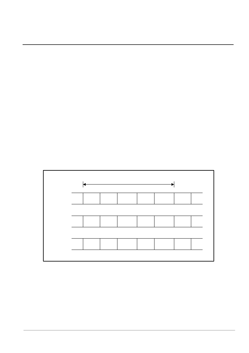
An example is shown in Figure 11 for a divide ratio of 596+2/5. The values for M, A, B are calculated using the integer
value (596) as in the previous example. The fractional denominator is programmed as 5 and the fractional numerator
as 2. At the end of the first count cycle (596) the fractional counter is incremented to 2. At the end of the third count
cycle the fractional N counter overflows, incrementing the A counter by 1 which gives a subsequent count cycle of
597. After five count cycles the sequence repeats with a total count of 2982 over the five count cycle giving a mean
value of 596 + 2/5.
Figure 11 - UHF Synthesizer - Fractional N Operation
A result of this count sequence is that the output phase of the total counter changes through the count cycle, which
causes the output pulse from the phase detector, and therefore the charge pump, to vary. This would cause large
fractional spurs on the synthesizer output. These spurs can be compensated by applying a current pulse with the
opposite polarity to the charge pump output. This compensation pulse has a fixed width of two reference clock
(TCXO) periods; the amplitude is proportional to the value in the fractional N counter. The correction current is scaled
by a 8 bit compensation DAC, with an externally provided input from the serial bus. This allows performance to be
optimized in a given application.
596
596
597
596
2
4
1
3
597
596
2
0
0
Total Count Cycle
Count Value
Fractional N
Counter
Initial A
Counter
Value
4
4
5
4
4
5
相關(guān)PDF資料 |
PDF描述 |
|---|---|
| ZL20250LCE | 2.5G Multimode Transceiver |
| ZL20250LCF | 2.5G Multimode Transceiver |
| ZL30100QDG1 | T1/E1 System Synchronizer |
| ZL30100 | T1/E1 System Synchronizer |
| ZL30100QDC | T1/E1 System Synchronizer |
相關(guān)代理商/技術(shù)參數(shù) |
參數(shù)描述 |
|---|---|
| ZL20250/LCE | 制造商:Microsemi Corporation 功能描述:RF TRNSCVR FM 56QFN - Bulk |
| ZL20250/LCF | 制造商:Microsemi Corporation 功能描述:RF TRNSCVR FM 56QFN - Bulk |
| ZL20250LCE | 制造商:ZARLINK 制造商全稱:Zarlink Semiconductor Inc 功能描述:2.5G Multimode Transceiver |
| ZL20250LCF | 制造商:ZARLINK 制造商全稱:Zarlink Semiconductor Inc 功能描述:2.5G Multimode Transceiver |
| ZL20B | 制造商:YEASHIN 制造商全稱:YEASHIN 功能描述:500 mW DO-35 Hermetically Sealed Glass Zener Voltage Regulators |
發(fā)布緊急采購,3分鐘左右您將得到回復。