- 您現(xiàn)在的位置:買賣IC網(wǎng) > PDF目錄359454 > W388CQX-7 INDUSTRIERELAIS FLANSCH 24VDC PDF資料下載
參數(shù)資料
| 型號: | W388CQX-7 |
| 英文描述: | INDUSTRIERELAIS FLANSCH 24VDC |
| 中文描述: | INDUSTRIERELAIS FLANSCH 24Vdc的 |
| 文件頁數(shù): | 94/210頁 |
| 文件大小: | 7067K |
| 代理商: | W388CQX-7 |
第1頁第2頁第3頁第4頁第5頁第6頁第7頁第8頁第9頁第10頁第11頁第12頁第13頁第14頁第15頁第16頁第17頁第18頁第19頁第20頁第21頁第22頁第23頁第24頁第25頁第26頁第27頁第28頁第29頁第30頁第31頁第32頁第33頁第34頁第35頁第36頁第37頁第38頁第39頁第40頁第41頁第42頁第43頁第44頁第45頁第46頁第47頁第48頁第49頁第50頁第51頁第52頁第53頁第54頁第55頁第56頁第57頁第58頁第59頁第60頁第61頁第62頁第63頁第64頁第65頁第66頁第67頁第68頁第69頁第70頁第71頁第72頁第73頁第74頁第75頁第76頁第77頁第78頁第79頁第80頁第81頁第82頁第83頁第84頁第85頁第86頁第87頁第88頁第89頁第90頁第91頁第92頁第93頁當(dāng)前第94頁第95頁第96頁第97頁第98頁第99頁第100頁第101頁第102頁第103頁第104頁第105頁第106頁第107頁第108頁第109頁第110頁第111頁第112頁第113頁第114頁第115頁第116頁第117頁第118頁第119頁第120頁第121頁第122頁第123頁第124頁第125頁第126頁第127頁第128頁第129頁第130頁第131頁第132頁第133頁第134頁第135頁第136頁第137頁第138頁第139頁第140頁第141頁第142頁第143頁第144頁第145頁第146頁第147頁第148頁第149頁第150頁第151頁第152頁第153頁第154頁第155頁第156頁第157頁第158頁第159頁第160頁第161頁第162頁第163頁第164頁第165頁第166頁第167頁第168頁第169頁第170頁第171頁第172頁第173頁第174頁第175頁第176頁第177頁第178頁第179頁第180頁第181頁第182頁第183頁第184頁第185頁第186頁第187頁第188頁第189頁第190頁第191頁第192頁第193頁第194頁第195頁第196頁第197頁第198頁第199頁第200頁第201頁第202頁第203頁第204頁第205頁第206頁第207頁第208頁第209頁第210頁

INTRODUCTION:
SOLID STATE RELAY (SSR)
is a relay with isolated input and output,
whose functions are achieved by means of electronic components without
the use of moving parts as found in Electromechanical relays.
PRINCIPLE OF OPERATION:
Solid State Relays are similar to Electromechanical relays, in that both use
a control circuit and a separate circuit for switching the load. When voltage
is applied to the input of the SSR, the relay is energized by a light emitting
diode. The light from the diode is beamed into a light sensitive semiconduc-
tor which, in the case of zero voltage crossover relays, conditions the
control circuit to turn on the output solid state switch at the next zero voltage
crossover. In the case of nonzero voltage crossover relays, the output solid
state switch is turned on at the precise voltage occurring at the time.
Removal of the input power disables the control circuit and the solid state
switch is turned off when the load current passes through the zero point of
its cycle.
APPLICATIONS:
Solid State Relays are specially suitable in many applications.
Listed below are some typical applications.
Microprocessor-based Controls.
Computers and Computer Peripherals.
Process control Systems using PLCs
Temperature Control Systems.
Business Machines
Medical Equipment
Uninterrupted Power Supplies (UPS).
Communication
Traffic Signals, etc.
APPLICATION AND SELECTION CRITERIA FOR SOLID STATE
RELAYS:
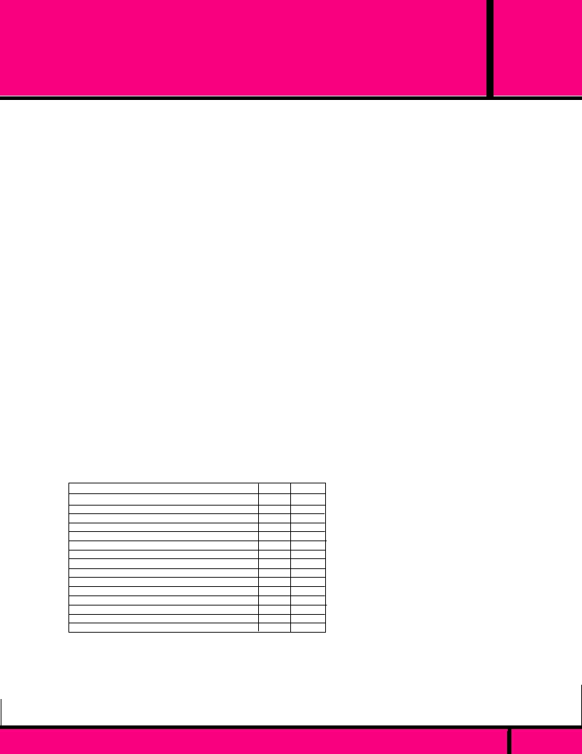
The Chart below indicates the areas in which SSR's (Solid State Relays) or
EMR (Electromechanical Relays) has better capabilities.
(X)
Indicates the
Better choice.
Long Life
Temperature Cycling
Shock and Vibration Resistant
Immunity to False Operation due to Transients
Generation of RFI, EMI
Multipole
Multithrow (SPDT)
Size (includes Heat Sink) for Equivalent Load Handling
Contact Bounce
Arcless Switching
Acoustic Noise
Zero Voltage Switching
Ease Of Diagnosing Malfunction
IC Compatibility
Immunity to Humidity, Salt Spray & Dirt
LOAD CONSIDERATIONS
A major portion of application problems with SSR's result from operating
conditions which specific loads impose upon an SSR. The following types
of loads point out the potential problems that can occur with SSR's.
LOAD CONSIDERATIONS (cont.)
DC LOADS:
All loads should be considered inductive and a Diode
should be placed across the load to absorb any inductive surge on
turnoff.
RESISTIVE LOADS:
Loads of constant value resistance are
probably the simplest application of SSR's. Proper attention to the
steady state current ratings and applied blocking voltage specifica-
tions normally will result in trouble-free operation.
LAMP LOADS
: Incandescent lamp loads, though basically
resistive, present some special problems. Because the resistance
of a cold tungsten filament is about five to ten percent of the
heated value, a large inrush current can occur. The period of the
inrush current can range from one half cycle to several cycles.,
depending on the thermal time constant of the filament. It is
essential to verify that this inrush current is within the surge
specifications of the SSR. Also check that the lamp rating of the
SSR is not exceeded. This is a UL rating based on the inrush of a
typical lamp. Because of the unusually low filament resistance at
the time of turn-on, a zero voltage turn-on characteristic is
particularly desirable with tungsten lamps.. It has been demon-
strated that a zero voltage turn-on can extend the life of tungsten
lamps by limiting inrush current.
CAPACITIVE LOADS:
Caution must be used with low impedance
capacitive loads to verify that the di/dt capabilities are not
exceeded. The di/dt of a discharged capacitive load with out
external limiting impedance can approach infinity. Zero voltage
turn-on is a particularly valuable means of limiting di/dt with
capacitive loads.
MOTORS:
Specifically, motors frequently have severe inrush
currents during starting and can impose unusual voltages during
turnoff. The inrush currents connected to mechanical loads having
high starting torque or inertia should be carefully determined to
verify that they are within the surge capabilities of the SSR. A
current shunt and Oscilloscope should be used to examine the
duration of the inrush current. Motor starting may frequently
reoccur at short intervals and the affect of repetitive inrush currents
on the thermal operating point of an SSR must be considered.
Check the motor operating current and locked rotor current versus
the SSR motor rating. The possibility of abnormally stalled rotor
conditions which draw much higher than normal currents should be
considered. An extended stalled rotor condition may require an
oversized SSR or fuse protection. The generated EMF of certain
motors can require an SSR to have a blocking voltage greater than
might be expected from steady state line voltage. The voltage
applied to an SSR by a motor circuit during turnoff should be
examined with an oscilloscope to verify hat the applied voltages
are safely below the specified SSR blocking voltages. Otherwise
lock-on or erratic turnoff of the motor may occur. Some motor
circuits may require higher than normal blocking voltage, transient
limiting devices, or other techniques to control the voltage which
must be blocked by an SSR during deceleration or direction
reversal.
SSR
X
EMR
X
X
X
X
X
X
X
X
X
X
X
X
X
X
C L A S S
SSR
APPLICATION DATA
PAGE 94
WEBSITE: www.magnecraft.com EMAIL:info@magnecraft.com FAX ON DEMAND 1-800/891-2957, DOCUMENT 100
相關(guān)PDF資料 |
PDF描述 |
|---|---|
| W388ACQX-10 | INDUSTRIERELAIS FLANSCH 230V |
| W171DIP-10 | RELAY REED DIL 24VDC |
| W199X-13 | HOCHLEISTUNGSRELAIS OFFEN 24VDC |
| W199AX-15 | RELAY OPEN CHASSIS 240VAC |
| W172DIP-5 | RELAY REED DIL 5VDC |
相關(guān)代理商/技術(shù)參數(shù) |
參數(shù)描述 |
|---|---|
| W388CQX-8 | 制造商:Magnecraft 功能描述: |
| W388DBCPX-3 | 制造商:Magnecraft 功能描述: |
| W388DBCPX5 | 制造商:Magnecraft 功能描述:3-5 Days |
| W388JCPX-11 | 制造商:Magnecraft 功能描述: |
| W388JCPX-3 | 制造商:Magnecraft 功能描述: |
發(fā)布緊急采購,3分鐘左右您將得到回復(fù)。