- 您現在的位置:買賣IC網 > PDF目錄359454 > W388CQX-7 INDUSTRIERELAIS FLANSCH 24VDC PDF資料下載
參數資料
| 型號: | W388CQX-7 |
| 英文描述: | INDUSTRIERELAIS FLANSCH 24VDC |
| 中文描述: | INDUSTRIERELAIS FLANSCH 24Vdc的 |
| 文件頁數: | 129/210頁 |
| 文件大小: | 7067K |
| 代理商: | W388CQX-7 |
第1頁第2頁第3頁第4頁第5頁第6頁第7頁第8頁第9頁第10頁第11頁第12頁第13頁第14頁第15頁第16頁第17頁第18頁第19頁第20頁第21頁第22頁第23頁第24頁第25頁第26頁第27頁第28頁第29頁第30頁第31頁第32頁第33頁第34頁第35頁第36頁第37頁第38頁第39頁第40頁第41頁第42頁第43頁第44頁第45頁第46頁第47頁第48頁第49頁第50頁第51頁第52頁第53頁第54頁第55頁第56頁第57頁第58頁第59頁第60頁第61頁第62頁第63頁第64頁第65頁第66頁第67頁第68頁第69頁第70頁第71頁第72頁第73頁第74頁第75頁第76頁第77頁第78頁第79頁第80頁第81頁第82頁第83頁第84頁第85頁第86頁第87頁第88頁第89頁第90頁第91頁第92頁第93頁第94頁第95頁第96頁第97頁第98頁第99頁第100頁第101頁第102頁第103頁第104頁第105頁第106頁第107頁第108頁第109頁第110頁第111頁第112頁第113頁第114頁第115頁第116頁第117頁第118頁第119頁第120頁第121頁第122頁第123頁第124頁第125頁第126頁第127頁第128頁當前第129頁第130頁第131頁第132頁第133頁第134頁第135頁第136頁第137頁第138頁第139頁第140頁第141頁第142頁第143頁第144頁第145頁第146頁第147頁第148頁第149頁第150頁第151頁第152頁第153頁第154頁第155頁第156頁第157頁第158頁第159頁第160頁第161頁第162頁第163頁第164頁第165頁第166頁第167頁第168頁第169頁第170頁第171頁第172頁第173頁第174頁第175頁第176頁第177頁第178頁第179頁第180頁第181頁第182頁第183頁第184頁第185頁第186頁第187頁第188頁第189頁第190頁第191頁第192頁第193頁第194頁第195頁第196頁第197頁第198頁第199頁第200頁第201頁第202頁第203頁第204頁第205頁第206頁第207頁第208頁第209頁第210頁

236/237/238
SERIES
12 PIN, 10 AMP, TIME DELAY RELAY
PAGE 129
WEBSITE: www.magnecraft.com EMAIL:info@magnecraft.com FAX ON DEMAND 1-800/891-2957, DOCUMENT 100
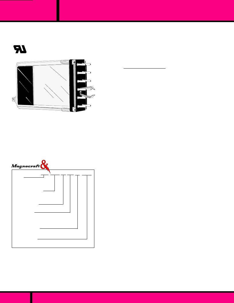
236 ABX P 020 120A
Typical Part Number
Series
236
- ON DELAY
237
- OFF DELAY
238
-
BATCH CONTROL INTERVAL
Code 012**- 12 Second timing not available on 237 & 238 models.
(F *
Models) - timing code does not apply. Specify single delay time requirement.
Example
of typical fixed time delay relay part number-
236XBXP-3.5F-120A
(ON DELAY, DPDT, 3.5 SEC FIXED, 120 VAC INPUT POWER).
NOTES:
1.
236,237,238 -
External resistor (to program time delay) or jumper (for
built-in timing) must be connected to terminals 8 & 9.
2.
237
models require an external control switch between terminals 5 & 6.
3.
238
switches contacts when input power is applied and starts timing.
Contacts switch back to original position at end of timing cycle. Power must
be removed to reset timer. If input power is interupted during the timing
cycle, timing ends immediately and the relay resets.
4. Dielectric withstanding voltage testing of the Control circuit may damage
the solid state components.
SEE SECTION 10 FOR MATING SOCKETS
GENERAL SPECIFICATIONS
The Series 236, 237 and 238 Time Delay Relay
consists
of a standard 219 industrial relay and a solid state timing
module to provide delayed transfer of relay contacts after
application of power or activation of control switch. The
relay and timing module are enclosed in a flame resistant
polycarbonate cover.
UL Recognized
File No. E13224
SERIES 236 ON DELAY, 237 OFF DELAY & 238 BATCH CONTROL
INTERVAL (SEE NOTE 3)
AC OR DC INPUT
DPDT OR DPDT WITH 1 N.O. CONTACT ON SERIES 236 & 238
12 PIN PLUG-IN WITH LOCKING CLIP
TIMING: SCREWDRIVER ADJUSTABLE OR FIXED
AC:
24 to 240,
DC:
12 to 125
AC - 85% of Nominal
DC - 80% of Nominal
110% of nominal voltage
Silver Cadmium Oxide.
10 Amps @ 120 VAC res.
10 Amps @ 28 VDC
DC:
±
3%: @ 20C. AC:
±
3% +16 mS
@ 20C.
Adjustable:
±
10% Within temperature
& voltage range. Fixed:
±
10% @ 25C
100 mS (for timing cycle up to 60 sec.
150 mS for timing cycle 60 to 300 sec.
500 V rms across open contacts,
1500 V rms between output contacts
and ground (Locking clip). (See note 4).
1000 Megohms min. @ 500 VDC.
5 mS, 0 to 2000 V 20 uSec peak
No false contacting if power is
interupted during timing.
DC operated are polarity protected. but
will not operate if polarity is reversed.
- 10C to +70 C
10 Million Operations no load
100,000 Operations @ Rated Load.
Clear Polycarbonate
8.6 oz approx. (244 g)
Contact Arrangements
ABX
(DPDT & 1 N.O. Contact) 236 &
238 only).
XBX
(DPDT)
Mounting Options
P
(Plug-in)
Timing Ranges
0.2 - 12 Sec -
Code 012**
0.2 - 20 Sec -
Code 020
2.0 - 200 Sec -
Code 200
Adjustment Options
Adjustment Screw) -
No Code
Fixed Delay - Specify Fixed Time &
Code F *
Operating Voltage
AC; 24, 48, 120, 240
(Add "A" )
DC; 12, 24, 48, 115-125
(Add "D")
Struthers-Dunn
INPUT
Nominal Voltage:
Minimum Oper. Voltage:
Max. allowed voltage:
CONTACTS
Contact Material:
Rating:
OPERATIONAL CHARACTERISTICS
Repeatability:
Accuracy:
Min. waiting time before starting
next cycle (Reset Time):
INSULATION CHARACTERISTICS
Dielectric Strength:
Insulation Resistance:
Transient Protection:
False Contacting:
Inverse polarity protection:
ENVIRONMENTAL CAPABILITIES
Ambient Temperature Rating:
LIFE EXPECTANCY
Mechanical:
Electrical:
MISCELLANEOUS
Enclosure:
Weight:
相關PDF資料 |
PDF描述 |
|---|---|
| W388ACQX-10 | INDUSTRIERELAIS FLANSCH 230V |
| W171DIP-10 | RELAY REED DIL 24VDC |
| W199X-13 | HOCHLEISTUNGSRELAIS OFFEN 24VDC |
| W199AX-15 | RELAY OPEN CHASSIS 240VAC |
| W172DIP-5 | RELAY REED DIL 5VDC |
相關代理商/技術參數 |
參數描述 |
|---|---|
| W388CQX-8 | 制造商:Magnecraft 功能描述: |
| W388DBCPX-3 | 制造商:Magnecraft 功能描述: |
| W388DBCPX5 | 制造商:Magnecraft 功能描述:3-5 Days |
| W388JCPX-11 | 制造商:Magnecraft 功能描述: |
| W388JCPX-3 | 制造商:Magnecraft 功能描述: |
發(fā)布緊急采購,3分鐘左右您將得到回復。