- 您現(xiàn)在的位置:買賣IC網(wǎng) > PDF目錄25648 > ST72361AR9TC (STMICROELECTRONICS) 8-BIT, FLASH, 8 MHz, MICROCONTROLLER, PQFP64 PDF資料下載
參數(shù)資料
| 型號(hào): | ST72361AR9TC |
| 廠商: | STMICROELECTRONICS |
| 元件分類: | 微控制器/微處理器 |
| 英文描述: | 8-BIT, FLASH, 8 MHz, MICROCONTROLLER, PQFP64 |
| 封裝: | 10 X 10 MM, ROHS COMPLIANT, PLASTIC, TQFP-64 |
| 文件頁(yè)數(shù): | 54/224頁(yè) |
| 文件大小: | 4821K |
| 代理商: | ST72361AR9TC |
第1頁(yè)第2頁(yè)第3頁(yè)第4頁(yè)第5頁(yè)第6頁(yè)第7頁(yè)第8頁(yè)第9頁(yè)第10頁(yè)第11頁(yè)第12頁(yè)第13頁(yè)第14頁(yè)第15頁(yè)第16頁(yè)第17頁(yè)第18頁(yè)第19頁(yè)第20頁(yè)第21頁(yè)第22頁(yè)第23頁(yè)第24頁(yè)第25頁(yè)第26頁(yè)第27頁(yè)第28頁(yè)第29頁(yè)第30頁(yè)第31頁(yè)第32頁(yè)第33頁(yè)第34頁(yè)第35頁(yè)第36頁(yè)第37頁(yè)第38頁(yè)第39頁(yè)第40頁(yè)第41頁(yè)第42頁(yè)第43頁(yè)第44頁(yè)第45頁(yè)第46頁(yè)第47頁(yè)第48頁(yè)第49頁(yè)第50頁(yè)第51頁(yè)第52頁(yè)第53頁(yè)當(dāng)前第54頁(yè)第55頁(yè)第56頁(yè)第57頁(yè)第58頁(yè)第59頁(yè)第60頁(yè)第61頁(yè)第62頁(yè)第63頁(yè)第64頁(yè)第65頁(yè)第66頁(yè)第67頁(yè)第68頁(yè)第69頁(yè)第70頁(yè)第71頁(yè)第72頁(yè)第73頁(yè)第74頁(yè)第75頁(yè)第76頁(yè)第77頁(yè)第78頁(yè)第79頁(yè)第80頁(yè)第81頁(yè)第82頁(yè)第83頁(yè)第84頁(yè)第85頁(yè)第86頁(yè)第87頁(yè)第88頁(yè)第89頁(yè)第90頁(yè)第91頁(yè)第92頁(yè)第93頁(yè)第94頁(yè)第95頁(yè)第96頁(yè)第97頁(yè)第98頁(yè)第99頁(yè)第100頁(yè)第101頁(yè)第102頁(yè)第103頁(yè)第104頁(yè)第105頁(yè)第106頁(yè)第107頁(yè)第108頁(yè)第109頁(yè)第110頁(yè)第111頁(yè)第112頁(yè)第113頁(yè)第114頁(yè)第115頁(yè)第116頁(yè)第117頁(yè)第118頁(yè)第119頁(yè)第120頁(yè)第121頁(yè)第122頁(yè)第123頁(yè)第124頁(yè)第125頁(yè)第126頁(yè)第127頁(yè)第128頁(yè)第129頁(yè)第130頁(yè)第131頁(yè)第132頁(yè)第133頁(yè)第134頁(yè)第135頁(yè)第136頁(yè)第137頁(yè)第138頁(yè)第139頁(yè)第140頁(yè)第141頁(yè)第142頁(yè)第143頁(yè)第144頁(yè)第145頁(yè)第146頁(yè)第147頁(yè)第148頁(yè)第149頁(yè)第150頁(yè)第151頁(yè)第152頁(yè)第153頁(yè)第154頁(yè)第155頁(yè)第156頁(yè)第157頁(yè)第158頁(yè)第159頁(yè)第160頁(yè)第161頁(yè)第162頁(yè)第163頁(yè)第164頁(yè)第165頁(yè)第166頁(yè)第167頁(yè)第168頁(yè)第169頁(yè)第170頁(yè)第171頁(yè)第172頁(yè)第173頁(yè)第174頁(yè)第175頁(yè)第176頁(yè)第177頁(yè)第178頁(yè)第179頁(yè)第180頁(yè)第181頁(yè)第182頁(yè)第183頁(yè)第184頁(yè)第185頁(yè)第186頁(yè)第187頁(yè)第188頁(yè)第189頁(yè)第190頁(yè)第191頁(yè)第192頁(yè)第193頁(yè)第194頁(yè)第195頁(yè)第196頁(yè)第197頁(yè)第198頁(yè)第199頁(yè)第200頁(yè)第201頁(yè)第202頁(yè)第203頁(yè)第204頁(yè)第205頁(yè)第206頁(yè)第207頁(yè)第208頁(yè)第209頁(yè)第210頁(yè)第211頁(yè)第212頁(yè)第213頁(yè)第214頁(yè)第215頁(yè)第216頁(yè)第217頁(yè)第218頁(yè)第219頁(yè)第220頁(yè)第221頁(yè)第222頁(yè)第223頁(yè)第224頁(yè)
ST72361-Auto
147/224
LINSCI
SERIAL COMMUNICATION INTERFACE (LIN Mode) (Cont’d)
CONTROL REGISTER 2 (SCICR2)
Read/Write
Reset Value: 0000 0000 (00h)
Bits 7:2 Same function as in SCI mode, please re-
Bit 1 = RWU Receiver wake-up.
This bit determines if the SCI is in mute mode or
not. It is set and cleared by software and can be
cleared by hardware when a wake-up sequence is
recognized.
0: Receiver in active mode
1: Receiver in mute mode
Notes:
– Mute mode is recommended for detecting only
the Header and avoiding the reception of any
other characters. For more details please refer to
– In LIN slave mode, when RDRF is set, the soft-
ware can not set or clear the RWU bit.
Bit 0 = SBK Send break.
This bit set is used to send break characters. It is
set and cleared by software.
0: No break character is transmitted
1: Break characters are transmitted
Note: If the SBK bit is set to “1” and then to “0”, the
transmitter will send a BREAK word at the end of
the current word.
CONTROL REGISTER 3 (SCICR3)
Read/Write
Reset Value: 0000 0000 (00h)
Bit 7 = LDUM LIN Divider Update Method.
This bit is set and cleared by software and is also
cleared by hardware (when RDRF = 1). It is only
used in LIN Slave mode. It determines how the LIN
Divider can be updated by software.
0: LDIV is updated as soon as LPR is written (if no
Auto Synchronization update occurs at the
same time).
1: LDIV is updated at the next received character
(when RDRF = 1) after a write to the LPR regis-
ter
Notes:
- If no write to LPR is performed between the set-
ting of LDUM bit and the reception of the next
character, LDIV will be updated with the old value.
- After LDUM has been set, it is possible to reset
the LDUM bit by software. In this case, LDIV can
be modified by writing into LPR / LPFR registers.
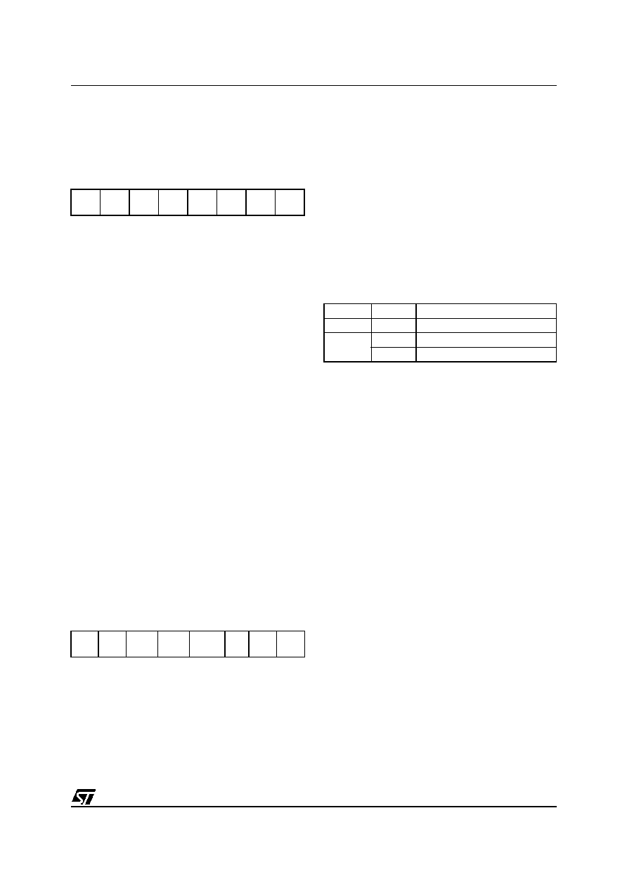
Bits 6:5 = LINE, LSLV LIN Mode Enable Bits.
These bits configure the LIN mode:
The LIN Master configuration enables:
The capability to send LIN Synch Breaks (13 low
bits) using the SBK bit in the SCICR2 register.
The LIN Slave configuration enables:
– The LIN Slave Baud Rate generator. The LIN
Divider (LDIV) is then represented by the LPR
and LPFR registers. The LPR and LPFR reg-
isters are read/write accessible at the address
of the SCIBRR register and the address of the
SCIETPR register
– Management of LIN Headers.
– LIN Synch Break detection (11-bit dominant).
– LIN Wake-Up method (see LHDM bit) instead
of the normal SCI Wake-Up method.
– Inhibition of Break transmission capability
(SBK has no effect)
– LIN Parity Checking (in conjunction with the
PCE bit)
Bit 4 = LASE LIN Auto Synch Enable.
This bit enables the Auto Synch Unit (ASU). It is
set and cleared by software. It is only usable in LIN
Slave mode.
0: Auto Synch Unit disabled
1: Auto Synch Unit enabled.
Bit 3 = LHDM LIN Header Detection Method
This bit is set and cleared by software. It is only us-
able in LIN Slave mode. It enables the Header De-
tection Method. In addition if the RWU bit in the
7
0
TIE
TCIE
RIE
ILIE
TE
RE
RWU
SBK
7
0
LDUM
LINE
LSLV
LASE
LHDM
LHIE LHDF
LSF
LINE
LSLV
Meaning
0
x
LIN mode disabled
1
0
LIN Master Mode
1
LIN Slave Mode
相關(guān)PDF資料 |
PDF描述 |
|---|---|
| ST72P361J4TA | 8-BIT, FLASH, 8 MHz, MICROCONTROLLER, PQFP44 |
| ST72F321BAR7TARE | 8-BIT, FLASH, 16 MHz, MICROCONTROLLER, PQFP64 |
| ST72P321B(AR6)TCXXXE | 8-BIT, MROM, 16 MHz, MICROCONTROLLER, PQFP64 |
| ST72F324BJ2TATRE | 8-BIT, FLASH, 8 MHz, MICROCONTROLLER, PQFP44 |
| ST72F324BK4TCE | 8-BIT, FLASH, 8 MHz, MICROCONTROLLER, PQFP32 |
相關(guān)代理商/技術(shù)參數(shù) |
參數(shù)描述 |
|---|---|
| ST72361K6T6 | 制造商:STMicroelectronics 功能描述:ROMLESS MICRO WITH 2 UART - Bulk |
| ST72371 | 制造商:STMICROELECTRONICS 制造商全稱:STMicroelectronics 功能描述:8-BIT MCUs WITH 16K ROM/OTP/EPROM,512 BYTES RAM, ADC, DAC (PWM), TIMER, I2C AND SCI |
| ST72371N4B1 | 制造商:STMICROELECTRONICS 制造商全稱:STMicroelectronics 功能描述:8-BIT MCUs WITH 16K ROM/OTP/EPROM,512 BYTES RAM, ADC, DAC (PWM), TIMER, I2C AND SCI |
| ST72371N4B1/XXX | 制造商:未知廠家 制造商全稱:未知廠家 功能描述:MICROCONTROLLER|8-BIT|ST72 CPU|CMOS|SDIP|56PIN|PLASTIC |
| ST72371N4T1 | 制造商:STMICROELECTRONICS 制造商全稱:STMicroelectronics 功能描述:8-BIT MCUs WITH 16K ROM/OTP/EPROM,512 BYTES RAM, ADC, DAC (PWM), TIMER, I2C AND SCI |
發(fā)布緊急采購(gòu),3分鐘左右您將得到回復(fù)。