- 您現(xiàn)在的位置:買賣IC網(wǎng) > PDF目錄372108 > SAA2500 (NXP Semiconductors N.V.) MPEG Audio Source Decoder PDF資料下載
參數(shù)資料
| 型號: | SAA2500 |
| 廠商: | NXP Semiconductors N.V. |
| 英文描述: | MPEG Audio Source Decoder |
| 中文描述: | MPEG音頻源解碼器 |
| 文件頁數(shù): | 5/47頁 |
| 文件大小: | 199K |
| 代理商: | SAA2500 |
第1頁第2頁第3頁第4頁當(dāng)前第5頁第6頁第7頁第8頁第9頁第10頁第11頁第12頁第13頁第14頁第15頁第16頁第17頁第18頁第19頁第20頁第21頁第22頁第23頁第24頁第25頁第26頁第27頁第28頁第29頁第30頁第31頁第32頁第33頁第34頁第35頁第36頁第37頁第38頁第39頁第40頁第41頁第42頁第43頁第44頁第45頁第46頁第47頁
September 1994
5
Philips Semiconductors
Preliminary specification
MPEG Audio Source Decoder
SAA2500
TMS
TDI
FSCLK384
FSCLKM
MCLK24
40
41
42
43
44
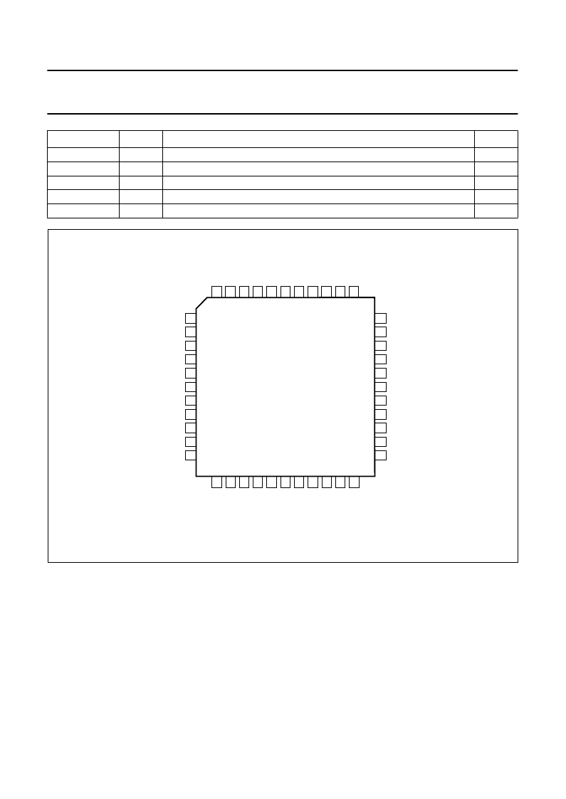
boundary scan test mode select input
boundary scan test data input
sample rate clock frequency indication input
sample rate clock source selection for the master input
master clock frequency indication
I
I
I
I
I
SYMBOL
PIN
DESCRIPTION
TYPE
Fig.2 Pin configuration.
handbook, full pagewidth
handbook, full pagewidth
1
2
3
4
5
6
7
8
9
10
11
33
32
31
30
29
28
27
26
25
24
23
1
1
1
1
1
1
1
1
2
2
2
4
4
4
4
4
3
3
3
3
3
3
TB
TI
TO
WS
SCK
GND
TA
SD
L3MODE
L3DATA
L3CLK
M
F
F
T
T
T
T
T
T
T
V
RESET
FSCLK
FSCLKIN
MCLK
V
GND
MCLKOUT
MCLKIN
X22OUT
X22IN
STOP
DD
U
C
C
C
G
C
C
C
C
C
C
SAA2500
(QFP44)
D
MGB490
FUNCTIONAL DESCRIPTION
Coding system
The perceptual audio encoding/decoding scheme defined
within the “ISO/IEC 11172-3 MPEG Standard”allows for a
high reduction in the amount of data needed for digital
audio whilst maintaining a high perceived sound quality.
The coding is based upon a psycho-acoustic model of the
human auditory system. The coding scheme exploits the
fact that the human ear does not perceive weak spectral
components that are in the proximity (both in time and
frequency) of loud components. This phenomenon is
called masking.
For layers I and II of ISO/MPEG the broadband audio
signal spectrum is split into 32 sub-bands of equal
bandwidth. For each sub-band signal a masking threshold
is calculated. The sub-band samples are then
re-quantized to such an accuracy that the spectral
distribution of the re-quantization noise does not exceed
the masking threshold. It is this reduction of representation
accuracy which yields the data reduction. The
re-quantized sub-band signals are multiplexed, together
with ancillary information regarding the actual
re-quantization, into a MPEG audio bitstream.
相關(guān)PDF資料 |
PDF描述 |
|---|---|
| SAA2500H | MPEG Audio Source Decoder |
| SAA2501 | Digital Audio Broadcast DAB decoder |
| SAA2501H | Digital Audio Broadcast DAB decoder |
| SAA2502 | ISO/MPEG Audio Source Decoder |
| SAA2502H | ISO/MPEG Audio Source Decoder |
相關(guān)代理商/技術(shù)參數(shù) |
參數(shù)描述 |
|---|---|
| SAA2500GP | 制造商:未知廠家 制造商全稱:未知廠家 功能描述:Video Processing/ENDEC for MPEG |
| SAA2500H | 制造商:PHILIPS 制造商全稱:NXP Semiconductors 功能描述:MPEG Audio Source Decoder |
| SAA2500HB-S | 制造商:未知廠家 制造商全稱:未知廠家 功能描述:Video Processing/ENDEC for MPEG |
| SAA2501 | 制造商:PHILIPS 制造商全稱:NXP Semiconductors 功能描述:Digital Audio Broadcast DAB decoder |
| SAA2501H | 制造商:PHILIPS 制造商全稱:NXP Semiconductors 功能描述:Digital Audio Broadcast DAB decoder |
發(fā)布緊急采購,3分鐘左右您將得到回復(fù)。