- 您現(xiàn)在的位置:買賣IC網(wǎng) > PDF目錄372108 > SAA2023 (NXP Semiconductors N.V.) Drive processor for DCC systems PDF資料下載
參數(shù)資料
| 型號: | SAA2023 |
| 廠商: | NXP Semiconductors N.V. |
| 英文描述: | Drive processor for DCC systems |
| 中文描述: | 戴納信貸驅動處理器的系統(tǒng) |
| 文件頁數(shù): | 31/56頁 |
| 文件大小: | 274K |
| 代理商: | SAA2023 |
第1頁第2頁第3頁第4頁第5頁第6頁第7頁第8頁第9頁第10頁第11頁第12頁第13頁第14頁第15頁第16頁第17頁第18頁第19頁第20頁第21頁第22頁第23頁第24頁第25頁第26頁第27頁第28頁第29頁第30頁當前第31頁第32頁第33頁第34頁第35頁第36頁第37頁第38頁第39頁第40頁第41頁第42頁第43頁第44頁第45頁第46頁第47頁第48頁第49頁第50頁第51頁第52頁第53頁第54頁第55頁第56頁

May 1994
31
Philips Semiconductors
Preliminary specification
Drive processor for DCC systems
SAA2023
V
DD7
This is the supply pin for the output buffers to the data lines
of the system RAM. It should always be connected
externally. Decouple this pin with a 22 nF capacitor to the
V
SS7
pin.
V
SS7
This is the ground supply pin for the output buffers of the
data lines of the system RAM. This pin is connected
internally to all the supply ground pins (V
SS1
to V
SS6
),
however it should always be connected externally.
Auxiliary envelope detection
INTMASK
INTMASK is a interrupt mask register. This register sets
the mode of operation for the interrupt interface, and is
writable only.
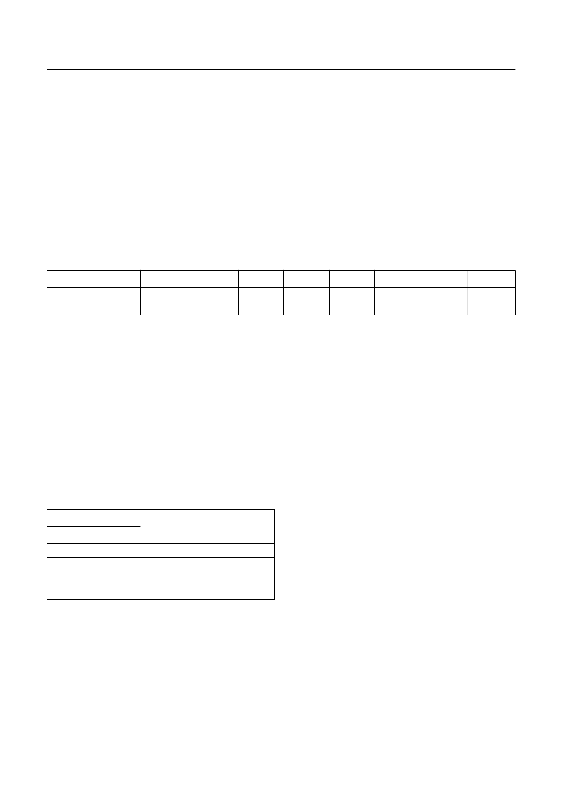
Table 22
Interrupt mask register.
Notes
1.
2.
3.
4.
5.
6.
Vup
≡
rising edge of VIRGIN interrupt.
AEup
≡
rising edge of AUX envelope interrupt.
AEdn
≡
falling edge of AUX envelope interrupt.
Lup
≡
rising edge of LABEL interrupt.
Ldn
≡
falling edge of LABEL interrupt.
ECZ
≡
AUX envelope counter has just reached zero interrupt.
BIT
7
6
5
4
3
2
1
0
Meaning
Default
BP1
0
BP0
0
Vup
(1)
0
AEup
(2)
0
AEdn
(3)
0
Lup
(4)
0
Ldn
(5)
0
ECZ
(6)
0
BP1
AND
BP0 (
BYPASS
)
If any of the bypass bits are HIGH then the interrupts are
not passed on to the microcontroller, instead the level of
the corresponding signal is available an the interrupt pin.
Table 23
BP1 and BP0.
Notes
1.
LAB = LABEL (HIGH if a LABEL condition is detected
in the envelope of the AUX channel).
VIR = VIRGIN (indicated by the total [continuous]
absence of signal on the AUX channel).
2.
3.
BP
EFFECT OF BYPASS
1
0
0
0
1
1
0
1
0
1
no bypass
LAB on L3INT pin; note 1
AENV on L3INT pin; note 2
VIR on L3INT pin; note 3
The AUX envelope information is only valid when the
digital equalizer is in search mode and when the tape
speed is between the values of
3 to 48
×
nominal tape speed. The timing relationships
between the AUX channel input signal, AENV, LAB and
VIR are shown in Figs 26 to 28. The delays t
d1
and t
d2
are
between 0.25 and 0.5t
AUX
(AUX envelope periods). The
delays t
d3
, t
d4
, t
d5
and t
d6
are between 2 and 6t
AUX
(AUX envelope periods).
When using the digital equalizer in search mode first
program the digital equalizer to search mode, then
program the INTMASK register.
MASK
If the BP1 and BP0 bits are LOW then the mask bits take
effect. Any combination of the mask bits may be HIGH,
enabling the corresponding interrupts. The interrupt pin
L3INT is active LOW when used for interrupts and active
HIGH when used for bypassing. So if it is not in bypass
mode and at least one of the interrupts has occurred it will
go LOW and stays LOW until DEQ status byte 0 has been
read. Extra interrupts that occur after the first interrupt and
before the DEQ status byte 0 is read are seen in the status
register. Extra interrupts that occur after the status byte
相關PDF資料 |
PDF描述 |
|---|---|
| SAA2023H | RES 4.53K OHM 1/16W 0.5% 0402SMD |
| SAA2500 | MPEG Audio Source Decoder |
| SAA2500H | MPEG Audio Source Decoder |
| SAA2501 | Digital Audio Broadcast DAB decoder |
| SAA2501H | Digital Audio Broadcast DAB decoder |
相關代理商/技術參數(shù) |
參數(shù)描述 |
|---|---|
| SAA2023GP | 制造商:PHILIPS 制造商全稱:NXP Semiconductors 功能描述:Drive processor for DCC systems |
| SAA2023H | 制造商:PHILIPS 制造商全稱:NXP Semiconductors 功能描述:Drive processor for DCC systems |
| SAA2032 | 制造商:PHILIPS 制造商全稱:NXP Semiconductors 功能描述:Digital equalization for the tape drive processing of the DCC system |
| SAA2032GP | 制造商:PHILIPS 制造商全稱:NXP Semiconductors 功能描述:Digital equalization for the tape drive processing of the DCC system |
| SAA-21 | 制造商:GENERAL DEVICES 功能描述:CHASSIS SUPPORT ANGLES, Sold in a Set of 2 |
發(fā)布緊急采購,3分鐘左右您將得到回復。