- 您現(xiàn)在的位置:買(mǎi)賣(mài)IC網(wǎng) > PDF目錄230917 > RD-19240FG-A00 (DATA DEVICE CORP) SYNCHRO OR RESOLVER TO DIGITAL CONVERTER, PQFP52 PDF資料下載
參數(shù)資料
| 型號(hào): | RD-19240FG-A00 |
| 廠(chǎng)商: | DATA DEVICE CORP |
| 元件分類(lèi): | 位置變換器 |
| 英文描述: | SYNCHRO OR RESOLVER TO DIGITAL CONVERTER, PQFP52 |
| 封裝: | 10 X 10 MM, ROHS COMPLIANT, PLASTIC, MQFP-52 |
| 文件頁(yè)數(shù): | 14/19頁(yè) |
| 文件大小: | 432K |
| 代理商: | RD-19240FG-A00 |
第1頁(yè)第2頁(yè)第3頁(yè)第4頁(yè)第5頁(yè)第6頁(yè)第7頁(yè)第8頁(yè)第9頁(yè)第10頁(yè)第11頁(yè)第12頁(yè)第13頁(yè)當(dāng)前第14頁(yè)第15頁(yè)第16頁(yè)第17頁(yè)第18頁(yè)第19頁(yè)
4
Data Device Corporation
www.ddc-web.com
RD-19240
F-02/09-0
(CT). Its other input is the 14-bit digital angle
φ. Its output is an
analog error angle, or difference angle, between the two inputs.
The CT performs the ratiometric trigonometric computation of
SIN
θCOSφ - COSθSINφ = SIN(θ-φ) using amplifiers, switches,
logic and capacitors in precision ratios.
Note: The error output of the CT is normally sinusoidal, but
in LVDT mode, it is triangular (linear) and can be used
to convert any linear transducer output.
The converter accuracy is limited by the precision of the computing
elements in the CT. For enhanced accuracy, the CT in these convert-
ers uses capacitors in precision ratios, instead of the more conven-
tional precision resistor ratios. Capacitors used as computing ele-
ments with op-amps need to be sampled to eliminate voltage drifting.
Therefore, the circuits are sampled at a high rate (70 kHz) to eliminate
this drifting and at the same time to cancel out the op-amp offsets.
THEORY OF OPERATION
The RD-19240 converter is a single CMOS custom monolithic
chip. It is implemented using mixed signal CMOS technology
which merges precision analog circuitry with digital logic to form
a complete high-performance tracking resolver-to-digital convert-
er. For user flexibility and convenience, the converter bandwidth,
dynamics, and velocity scaling are externally set with passive
components.
FIGURE 1 is the RD-19240 Functional Block Diagram. The con-
verter operates with ±5 V DC power supplies. Analog signals are
referenced to analog ground, which is at ground potential. The
converter is made up of two main sections; a converter and a dig-
ital interface. The converter front-end consists of sine and cosine
differential input amplifiers. These inputs are protected to ±25 V
with 2 k
Ω resistors and diode clamps to the ±5 V DC supplies.
These amplifiers feed the high accuracy Control Transformer
PARAMETER
VALUE
UNIT
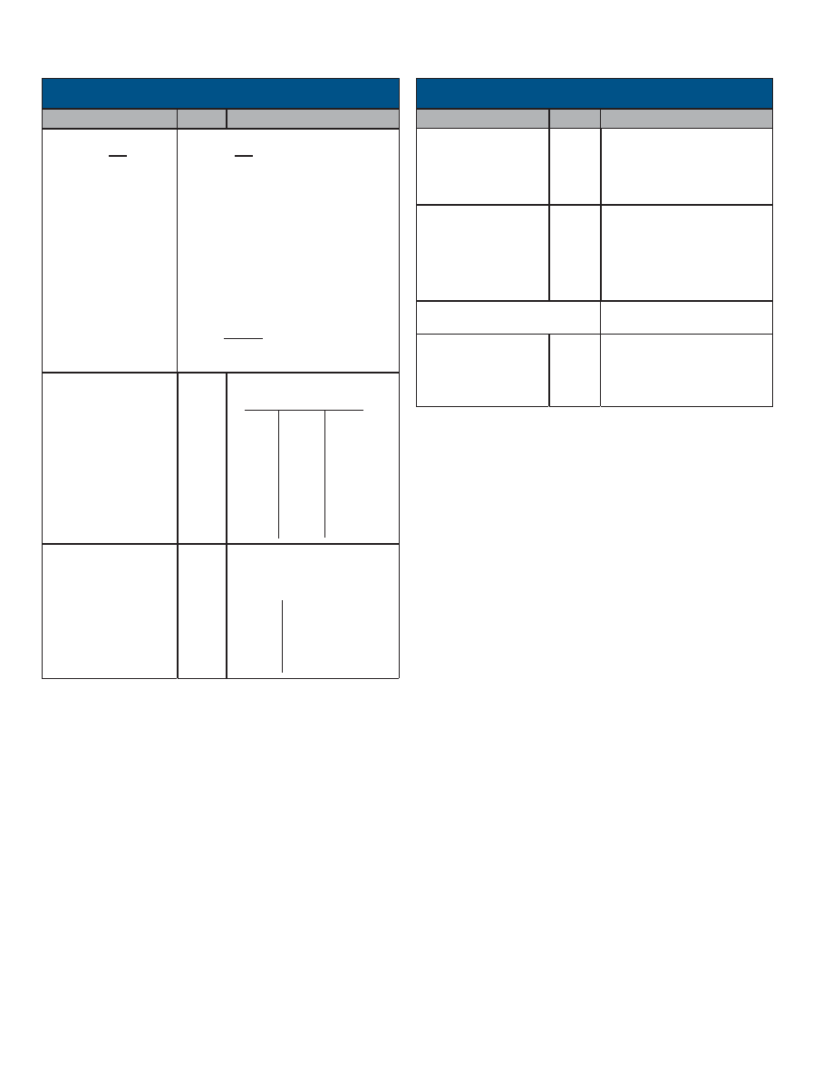
TABLE 1. RD-19240 SPECIFICATIONS (CONT.)
PARAMETER
VALUE
UNIT
TABLE 1. RD-19240 SPECIFICATIONS (CONT.)
POWER SUPPLIES
Nominal Voltage
Voltage Range
Max Volt. w/o Damage
Current
V
%
V
mA
(notes 6, 7 and 9)
+5
-5
±5
+7
-7
14 typ, 22 max (each)(Note 10)
TEMPERATURE RANGE
Operating (case)
-AXX
-2XX
-1XX
Storage
θJC FS package
°C
20°C/W
-40 to +125
-40 to +85
-55 to +125
-65 to +150
PHYSICAL
CHARACTERISTICS
Size
FS Package
52-pin MQFP
in(mm)
0.39 x 0.39 (10.0 x 10.0)
MOISTURE SENSITIVITY
LEVEL
Level 2 tested in accordance with
JDEC spec J-STD-020
DYNAMIC
CHARACTERISTICS
Resolution
Tracking Rate-min (note 4)
Bandwidth(Closed Loop) Max
Ka (acceleration constant
- see note 2)
A1
A2
A
B
Acceleration (1 LSB lag)
Settling Time(179° step)
bits
rps
Hz
1/sec2
1/sec
deg/s2
msec
(at maximum bandwidth)
(Note 9)
10
12
14
1152
288
72
1200
600
5.7M
1.4M
19.5
4.9
295k
2400
1200
600
2M
500k
30k
48
20
DIGITAL INPUT/OUTPUT
(CONT) (NOTE 6)
Built-in-Test (BIT)
Drive Capability
A, B (note 12)
Zero Index Pulse (ZIP)
Logic 0 for BIT condition.
±100 LSBs of error with a filter of 500 s
total, Loss-of-Signal (LOS) less than 500 mV,
or Loss-of-Reference (LOR) less than 500 mV.
50 pF+
Logic 0; 1 TTL load, =1.6 mA at 0.4 V max.
Logic 1; 10 TTL loads, =0.4 mA at 2.8 V min
Logic 0; 100 mV max. driving CMOS
Logic 1; +5 V supply minus 100 mV min dri-
ving CMOS High Z; 10 uA || 5 pF max.
Incremental Encoder Output
With the ZIP_EN pin tied to ground “Logic
0,” this ZIP output is active
VELOCITY
CHARACTERISTICS
Polarity
Voltage Range(Full Scale)
Scale Factor Error
Reversal Error
Linearity
Zero Offset
Zero Offset TC
Load
(note 12)
V
%
mV
V/C
k
Ω
Positive for increasing angle
±4 (at nominal ps)
10 typ.
20 max.
0.75 typ 1.3 max.
1.0 typ
1.5 max.
5 typ.
10 max.
15 typ.
8 min.
TABLE 1 notes:
1.
Unused data bits are set to logic “0”.
2.
For Ka definition, see the RD/RDC Series Converters Applications Manual
(MN-19220XX-001) acceleration lag section.
3.
If the frequency is 1kHz, then there may be 1 LSB of jitter at quadrant boundaries.
4.
See text, General Setup Considerations.
5.
When using internally generated -5V the internal -5V charge pump when measured
at the converter pin, may be as low as -20% (or -4V).
6.
Any unused input pins may be left floating. All TTL and CMOS input pins are
internally pulled up to +5 volts.
7.
High Z refers to parallel data only.
8.
In LVDT mode, bit 12 is LSB for 10-bit mode resolution.
9. See recommendation #1 under General Setup Conditions section.
10. Maximum current with Rset = 23.1k Ohm.
11. When in overload condition the converter will not operate to specification and will
not be damaged.
12. Dynamic accuracy may be degraded in high accuracy bandwidth system
applications. See Theory of Operation section for details.
相關(guān)PDF資料 |
PDF描述 |
|---|---|
| RD-14597F1-514K | SYNCHRO OR RESOLVER TO DIGITAL CONVERTER, CDFP36 |
| RD-14597F1-554W | SYNCHRO OR RESOLVER TO DIGITAL CONVERTER, CDFP36 |
| RD-14597F1-572Z | SYNCHRO OR RESOLVER TO DIGITAL CONVERTER, CDFP36 |
| RD-14597F1-592K | SYNCHRO OR RESOLVER TO DIGITAL CONVERTER, CDFP36 |
| RD-14597F1-594Y | SYNCHRO OR RESOLVER TO DIGITAL CONVERTER, CDFP36 |
相關(guān)代理商/技術(shù)參數(shù) |
參數(shù)描述 |
|---|---|
| RD1-9320 | 制造商:STMicroelectronics 功能描述:MPU DEMO-BOARD |
| RD1950MPXM2010GS | 制造商:Freescale Semiconductor 功能描述:WATER LEVEL REFERENCE DESIGN - Bulk |
| RD1986MMA2260D | 功能描述:加速傳感器開(kāi)發(fā)工具 TRIAX REF DSGN 3-AXIS FOR MMA2260D RoHS:否 制造商:Murata 工具用于評(píng)估:SCA3100-D04 加速:2 g 傳感軸:Triple Axis 接口類(lèi)型:SPI 工作電壓:3.3 V |
| RD1986MMA6260Q | 功能描述:加速傳感器開(kāi)發(fā)工具 TRIAX REF DSGN 3-AXIS FOR NMA6260Q RoHS:否 制造商:Murata 工具用于評(píng)估:SCA3100-D04 加速:2 g 傳感軸:Triple Axis 接口類(lèi)型:SPI 工作電壓:3.3 V |
| RD1A-12S | 制造商:World Products 功能描述: |
發(fā)布緊急采購(gòu),3分鐘左右您將得到回復(fù)。