- 您現(xiàn)在的位置:買賣IC網(wǎng) > PDF目錄367723 > P83C591SFA (NXP SEMICONDUCTORS) Single-chip 8-bit microcontroller with CAN controller PDF資料下載
參數(shù)資料
| 型號: | P83C591SFA |
| 廠商: | NXP SEMICONDUCTORS |
| 元件分類: | 微控制器/微處理器 |
| 英文描述: | Single-chip 8-bit microcontroller with CAN controller |
| 中文描述: | 8-BIT, MROM, 16 MHz, MICROCONTROLLER, PQCC44 |
| 封裝: | PLASTIC, SOT-187-2, LCC-44 |
| 文件頁數(shù): | 22/161頁 |
| 文件大?。?/td> | 588K |
| 代理商: | P83C591SFA |
第1頁第2頁第3頁第4頁第5頁第6頁第7頁第8頁第9頁第10頁第11頁第12頁第13頁第14頁第15頁第16頁第17頁第18頁第19頁第20頁第21頁當(dāng)前第22頁第23頁第24頁第25頁第26頁第27頁第28頁第29頁第30頁第31頁第32頁第33頁第34頁第35頁第36頁第37頁第38頁第39頁第40頁第41頁第42頁第43頁第44頁第45頁第46頁第47頁第48頁第49頁第50頁第51頁第52頁第53頁第54頁第55頁第56頁第57頁第58頁第59頁第60頁第61頁第62頁第63頁第64頁第65頁第66頁第67頁第68頁第69頁第70頁第71頁第72頁第73頁第74頁第75頁第76頁第77頁第78頁第79頁第80頁第81頁第82頁第83頁第84頁第85頁第86頁第87頁第88頁第89頁第90頁第91頁第92頁第93頁第94頁第95頁第96頁第97頁第98頁第99頁第100頁第101頁第102頁第103頁第104頁第105頁第106頁第107頁第108頁第109頁第110頁第111頁第112頁第113頁第114頁第115頁第116頁第117頁第118頁第119頁第120頁第121頁第122頁第123頁第124頁第125頁第126頁第127頁第128頁第129頁第130頁第131頁第132頁第133頁第134頁第135頁第136頁第137頁第138頁第139頁第140頁第141頁第142頁第143頁第144頁第145頁第146頁第147頁第148頁第149頁第150頁第151頁第152頁第153頁第154頁第155頁第156頁第157頁第158頁第159頁第160頁第161頁
1999 Aug 19
22
Philips Semiconductors
Objective Specification
Single-chip 8-bit microcontroller with CAN controller
P8xC591
11 LOW POWER MODES
11.1
Stop Clock Mode
The static design enables the clock speed to be reduced
down to 0 MHz (stopped). When the oscillator is stopped,
the RAM and Special Function Registers retain their
values. This mode allows step-by-step utilization and
permits reduced system power consumption by lowering
the clock frequency down to any value. For lowest power
consumption the Power-down mode is suggested.
11.2
Idle Mode
In the Idle mode (see Table 7), the CPU puts itself to sleep
while all of the on-chip peripherals stay active. The
instruction to invoke the idle mode is the last instruction
executed in the normal operating mode before the Idle
mode is activated. The CPU contents, the on-chip RAM,
and all of the special function registers remain intact during
this mode. The Idle mode can be terminated either by any
enabled interrupt (at which time the process is picked up
at the interrupt service routine and continued), or by a
hardware reset which starts the processor in the same
manner as a Power-on reset.
11.3
Power-down Mode
To save even more power, a Power-down mode (see
Table 7) can be invoked by software. In this mode, the
oscillator is stopped and the instruction that invoked Power
Down is the last instruction executed. The on-chip RAM
and Special Function Registers retain their values down to
2.0 V and care must be taken to return V
CC
to the minimum
specified operating voltages before the Power-down Mode
is terminated.
A hardware reset or external interrupt can be used to exit
from Power-down. The Wake-up from Power-down bit,
WUPD (AUXR1.3) must be set in order for an interrupt to
cause a Wake-up from Power-down. Reset redefines all
the SFRs but does not change the on-chip RAM. A
Wake-up allows both the SFRs and the on-chip RAM to
retain their values.
To properly terminate Power-down the reset or external
interrupt should not be executed before V
CC
is restored to
its normal operating level and must be held active long
enough for the oscillator to restart and stabilize (normally
less than 10 ms).
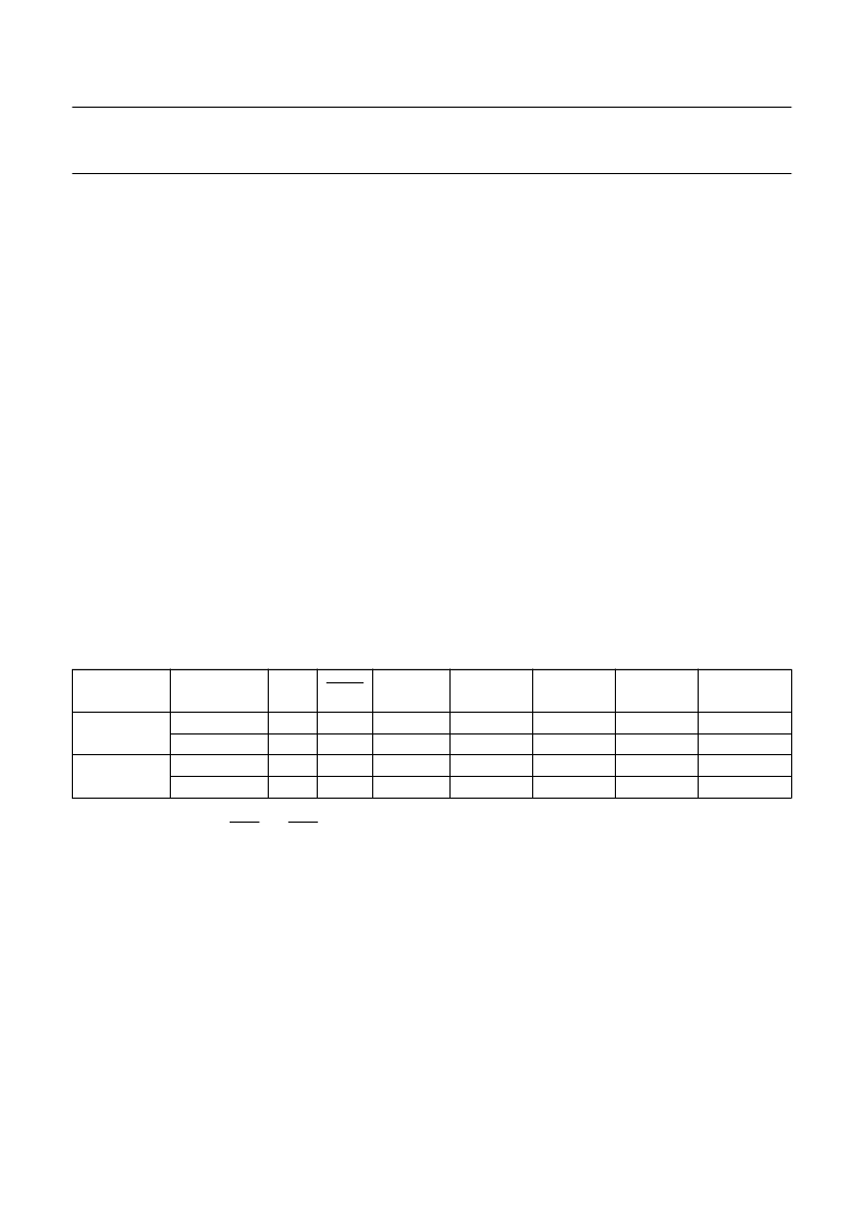
Table 7
Status of external pins during Idle and Power-down modes
With an external interrupt, INT0 and INT1 must be enabled and configured as level-sensitive. Holding the pin low restarts
the oscillator but bringing the pin back high completes the exit. Once the interrupt is serviced, the next instruction to be
executed after RETI will be the one following the instruction that put the device into Power-down.
MODE
MEMORY
ALE
PSEN
PORT 0
PORT 1
PORT 2
PORT 3
PWM0/
PWM1
Idle
internal
external
internal
external
1
1
0
0
1
1
0
0
port data
float
port data
float
port data
port data
port data
port data
port data
address
port data
port data
port data
port data
port data
port data
high
high
high
high
Power-down
相關(guān)PDF資料 |
PDF描述 |
|---|---|
| P87C591SFA | Single-chip 8-bit microcontroller with CAN controller |
| P80C591SFB | Single-chip 8-bit microcontroller with CAN controller |
| P83C591SFB | Single-chip 8-bit microcontroller with CAN controller |
| P87C591SFB | Single-chip 8-bit microcontroller with CAN controller |
| P80C591 | Single-chip 8-bit microcontroller with CAN controller |
相關(guān)代理商/技術(shù)參數(shù) |
參數(shù)描述 |
|---|---|
| P83C591SFB | 制造商:PHILIPS 制造商全稱:NXP Semiconductors 功能描述:Single-chip 8-bit microcontroller with CAN controller |
| P83C591VFA | 制造商:PHILIPS 制造商全稱:NXP Semiconductors 功能描述:Single-chip 8-bit microcontroller with CAN controller |
| P83C591VFB | 制造商:PHILIPS 制造商全稱:NXP Semiconductors 功能描述:Single-chip 8-bit microcontroller with CAN controller |
| P83C592 | 制造商:PHILIPS 制造商全稱:NXP Semiconductors 功能描述:8-bit microcontroller with on-chip CAN |
| P83C592FFA | 制造商:PHILIPS 制造商全稱:NXP Semiconductors 功能描述:8-bit microcontroller with on-chip CAN |
發(fā)布緊急采購,3分鐘左右您將得到回復(fù)。