- 您現(xiàn)在的位置:買賣IC網(wǎng) > PDF目錄45232 > MC68HC11P3CFN4R2 (MOTOROLA INC) 8-BIT, MROM, 4 MHz, MICROCONTROLLER, PQCC84 PDF資料下載
參數(shù)資料
| 型號(hào): | MC68HC11P3CFN4R2 |
| 廠商: | MOTOROLA INC |
| 元件分類: | 微控制器/微處理器 |
| 英文描述: | 8-BIT, MROM, 4 MHz, MICROCONTROLLER, PQCC84 |
| 封裝: | PLASTIC, LCC-84 |
| 文件頁(yè)數(shù): | 36/236頁(yè) |
| 文件大?。?/td> | 1232K |
| 代理商: | MC68HC11P3CFN4R2 |
第1頁(yè)第2頁(yè)第3頁(yè)第4頁(yè)第5頁(yè)第6頁(yè)第7頁(yè)第8頁(yè)第9頁(yè)第10頁(yè)第11頁(yè)第12頁(yè)第13頁(yè)第14頁(yè)第15頁(yè)第16頁(yè)第17頁(yè)第18頁(yè)第19頁(yè)第20頁(yè)第21頁(yè)第22頁(yè)第23頁(yè)第24頁(yè)第25頁(yè)第26頁(yè)第27頁(yè)第28頁(yè)第29頁(yè)第30頁(yè)第31頁(yè)第32頁(yè)第33頁(yè)第34頁(yè)第35頁(yè)當(dāng)前第36頁(yè)第37頁(yè)第38頁(yè)第39頁(yè)第40頁(yè)第41頁(yè)第42頁(yè)第43頁(yè)第44頁(yè)第45頁(yè)第46頁(yè)第47頁(yè)第48頁(yè)第49頁(yè)第50頁(yè)第51頁(yè)第52頁(yè)第53頁(yè)第54頁(yè)第55頁(yè)第56頁(yè)第57頁(yè)第58頁(yè)第59頁(yè)第60頁(yè)第61頁(yè)第62頁(yè)第63頁(yè)第64頁(yè)第65頁(yè)第66頁(yè)第67頁(yè)第68頁(yè)第69頁(yè)第70頁(yè)第71頁(yè)第72頁(yè)第73頁(yè)第74頁(yè)第75頁(yè)第76頁(yè)第77頁(yè)第78頁(yè)第79頁(yè)第80頁(yè)第81頁(yè)第82頁(yè)第83頁(yè)第84頁(yè)第85頁(yè)第86頁(yè)第87頁(yè)第88頁(yè)第89頁(yè)第90頁(yè)第91頁(yè)第92頁(yè)第93頁(yè)第94頁(yè)第95頁(yè)第96頁(yè)第97頁(yè)第98頁(yè)第99頁(yè)第100頁(yè)第101頁(yè)第102頁(yè)第103頁(yè)第104頁(yè)第105頁(yè)第106頁(yè)第107頁(yè)第108頁(yè)第109頁(yè)第110頁(yè)第111頁(yè)第112頁(yè)第113頁(yè)第114頁(yè)第115頁(yè)第116頁(yè)第117頁(yè)第118頁(yè)第119頁(yè)第120頁(yè)第121頁(yè)第122頁(yè)第123頁(yè)第124頁(yè)第125頁(yè)第126頁(yè)第127頁(yè)第128頁(yè)第129頁(yè)第130頁(yè)第131頁(yè)第132頁(yè)第133頁(yè)第134頁(yè)第135頁(yè)第136頁(yè)第137頁(yè)第138頁(yè)第139頁(yè)第140頁(yè)第141頁(yè)第142頁(yè)第143頁(yè)第144頁(yè)第145頁(yè)第146頁(yè)第147頁(yè)第148頁(yè)第149頁(yè)第150頁(yè)第151頁(yè)第152頁(yè)第153頁(yè)第154頁(yè)第155頁(yè)第156頁(yè)第157頁(yè)第158頁(yè)第159頁(yè)第160頁(yè)第161頁(yè)第162頁(yè)第163頁(yè)第164頁(yè)第165頁(yè)第166頁(yè)第167頁(yè)第168頁(yè)第169頁(yè)第170頁(yè)第171頁(yè)第172頁(yè)第173頁(yè)第174頁(yè)第175頁(yè)第176頁(yè)第177頁(yè)第178頁(yè)第179頁(yè)第180頁(yè)第181頁(yè)第182頁(yè)第183頁(yè)第184頁(yè)第185頁(yè)第186頁(yè)第187頁(yè)第188頁(yè)第189頁(yè)第190頁(yè)第191頁(yè)第192頁(yè)第193頁(yè)第194頁(yè)第195頁(yè)第196頁(yè)第197頁(yè)第198頁(yè)第199頁(yè)第200頁(yè)第201頁(yè)第202頁(yè)第203頁(yè)第204頁(yè)第205頁(yè)第206頁(yè)第207頁(yè)第208頁(yè)第209頁(yè)第210頁(yè)第211頁(yè)第212頁(yè)第213頁(yè)第214頁(yè)第215頁(yè)第216頁(yè)第217頁(yè)第218頁(yè)第219頁(yè)第220頁(yè)第221頁(yè)第222頁(yè)第223頁(yè)第224頁(yè)第225頁(yè)第226頁(yè)第227頁(yè)第228頁(yè)第229頁(yè)第230頁(yè)第231頁(yè)第232頁(yè)第233頁(yè)第234頁(yè)第235頁(yè)第236頁(yè)
MOTOROLA
8-8
MC68HC11P2
TIMING SYSTEM
8
OC1 is different from the other output compares in that a successful OC1 compare can affect any
or all ve of the OC pins. The OC1 output action taken when a match is found is controlled by two
8-bit registers with three bits unimplemented: the output compare 1 mask register, OC1M, and the
output compare 1 data register, OC1D. OC1M species which port A outputs are to be used, and
OC1D species what data is placed on these port pins.
8.3.1
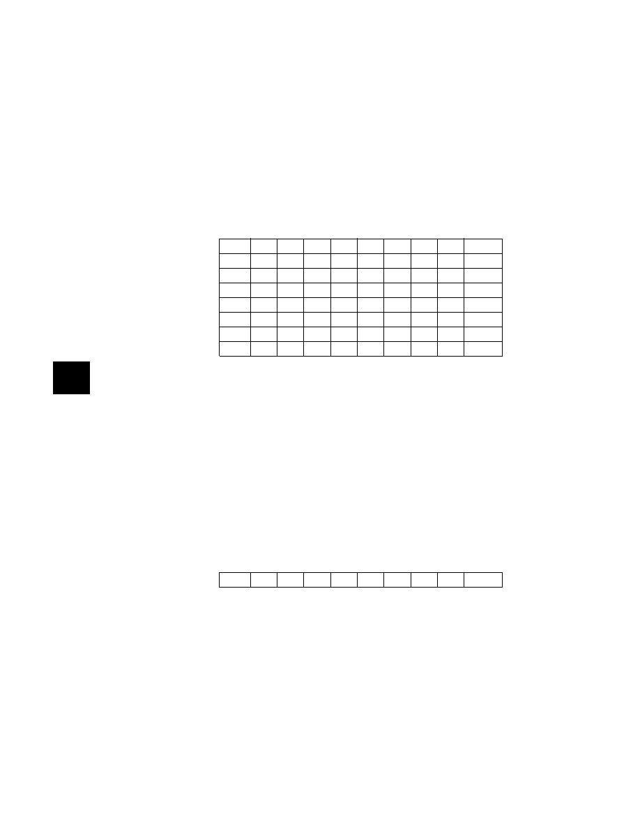
TOC1–TOC4 — Timer output compare registers
All output compare registers are 16-bit read-write. Each is initialized to $FFFF at reset. If an output
compare register is not used for an output compare function, it can be used as a storage location.
A write to the high-order byte of an output compare register pair inhibits the output compare
function for one bus cycle. This inhibition prevents inappropriate subsequent comparisons.
Coherency requires a complete 16-bit read or write. However, if coherency is not needed, byte
accesses can be used.
For output compare functions, write a comparison value to output compare registers TOC1–TOC4
and TI4/O5. When TCNT value matches the comparison value, specied pin actions occur.
All TOCx register pairs reset to ones ($FFFF).
8.3.2
CFORC — Timer compare force register
The CFORC register allows forced early compares. FOC[1:5] correspond to the ve output
compares. These bits are set for each output compare that is to be forced. The action taken as a
result of a forced compare is the same as if there were a match between the OCx register and the
free-running counter, except that the corresponding interrupt status ag bits are not set. The
Address
bit 7
bit 6
bit 5
bit 4
bit 3
bit 2
bit 1
bit 0
State
on reset
Timer output compare 1 (TOC1) high
$0016
(bit 15)
(14)
(13)
(12)
(11)
(10)
(9)
(bit 8) 1111 1111
Timer output compare 1 (TOC1) low
$0017
(bit 7)
(6)
(5)
(4)
(3)
(2)
(1)
(bit 0) 1111 1111
Timer output compare 2 (TOC2) high
$0018
(bit 15)
(14)
(13)
(12)
(11)
(10)
(9)
(bit 8) 1111 1111
Timer output compare 2 (TOC2) low
$0019
(bit 7)
(6)
(5)
(4)
(3)
(2)
(1)
(bit 0) 1111 1111
Timer output compare 3 (TOC3) high
$001A
(bit 15)
(14)
(13)
(12)
(11)
(10)
(9)
(bit 8) 1111 1111
Timer output compare 3 (TOC3) low
$001B
(bit 7)
(6)
(5)
(4)
(3)
(2)
(1)
(bit 0) 1111 1111
Timer output compare 4 (TOC4) high
$001C
(bit 15)
(14)
(13)
(12)
(11)
(10)
(9)
(bit 8) 1111 1111
Timer output compare 4 (TOC4) low
$001D
(bit 7)
(6)
(5)
(4)
(3)
(2)
(1)
(bit 0) 1111 1111
Address
bit 7
bit 6
bit 5
bit 4
bit 3
bit 2
bit 1
bit 0
State
on reset
Timer compare force (CFORC)
$000B
FOC1
FOC2
FOC3
FOC4
FOC5
0
0000 0000
相關(guān)PDF資料 |
PDF描述 |
|---|---|
| MC68HC11P1CFN4R2 | 8-BIT, EEPROM, 4 MHz, MICROCONTROLLER, PQCC84 |
| MC68HC11P2BCFN4R2 | 8-BIT, MROM, 4 MHz, MICROCONTROLLER, PQCC84 |
| MC68HC11PH8CPV3 | 8-BIT, MROM, 3 MHz, MICROCONTROLLER, PQFP112 |
| MC68S711PH8CFN4 | 8-BIT, OTPROM, 4 MHz, MICROCONTROLLER, PQCC84 |
| MC68S711PH8CFS3 | 8-BIT, UVPROM, 3 MHz, MICROCONTROLLER, CQCC84 |
相關(guān)代理商/技術(shù)參數(shù) |
參數(shù)描述 |
|---|---|
| MC68HC16Z1CAG | 制造商:Freescale Semiconductor 功能描述: |
| MC68HC16Z1CAG16 | 功能描述:16位微控制器 - MCU 16 BIT MCU 1K RAM RoHS:否 制造商:Texas Instruments 核心:RISC 處理器系列:MSP430FR572x 數(shù)據(jù)總線寬度:16 bit 最大時(shí)鐘頻率:24 MHz 程序存儲(chǔ)器大小:8 KB 數(shù)據(jù) RAM 大小:1 KB 片上 ADC:Yes 工作電源電壓:2 V to 3.6 V 工作溫度范圍:- 40 C to + 85 C 封裝 / 箱體:VQFN-40 安裝風(fēng)格:SMD/SMT |
| MC68HC16Z1CAG16 | 制造商:Freescale Semiconductor 功能描述:IC16-BIT MICROCONTROLLER |
| MC68HC16Z1CAG20 | 功能描述:16位微控制器 - MCU 16 BIT MCU 1K RAM RoHS:否 制造商:Texas Instruments 核心:RISC 處理器系列:MSP430FR572x 數(shù)據(jù)總線寬度:16 bit 最大時(shí)鐘頻率:24 MHz 程序存儲(chǔ)器大小:8 KB 數(shù)據(jù) RAM 大小:1 KB 片上 ADC:Yes 工作電源電壓:2 V to 3.6 V 工作溫度范圍:- 40 C to + 85 C 封裝 / 箱體:VQFN-40 安裝風(fēng)格:SMD/SMT |
| MC68HC16Z1CAG20 | 制造商:Freescale Semiconductor 功能描述:Microcontroller |
發(fā)布緊急采購(gòu),3分鐘左右您將得到回復(fù)。