- 您現(xiàn)在的位置:買賣IC網(wǎng) > PDF目錄384656 > MAX2101CMQ (MAXIM INTEGRATED PRODUCTS INC) 16-Bit Buffers/Drivers With 3-State Outputs 48-TSSOP -40 to 85 PDF資料下載
參數(shù)資料
| 型號: | MAX2101CMQ |
| 廠商: | MAXIM INTEGRATED PRODUCTS INC |
| 元件分類: | 消費家電 |
| 英文描述: | 16-Bit Buffers/Drivers With 3-State Outputs 48-TSSOP -40 to 85 |
| 中文描述: | SPECIALTY CONSUMER CIRCUIT, PQFP100 |
| 封裝: | METRIC, QFP-100 |
| 文件頁數(shù): | 15/24頁 |
| 文件大?。?/td> | 217K |
| 代理商: | MAX2101CMQ |
Filter Temperature Compensation
In both techniques discussed above, the ratio R
F
/R
TC
deter-
mines the compensation required to produce a
filter response with 0TC. As noted in the VPTAT vs.
Temperature graph in the Typical Operating Characteristics
this ratio should be set at 0.8.
Baseband Offset Correc tion
The MAX2101 integrates a high level of RF signal pro-
cessing, and applies substantial gain from the IF inputs
to the baseband signals applied to the ADC. Offset in
the signal path can seriously decrease the compo-
nent’s dynamic range, and variation in offset between I
and Q channels can seriously degrade overall receiver
performance. Several circuit design techniques are
used to minimize offset within the chip. However, two
characteristics of the component contribute to offset in
the signal path.
The off-chip tank network for the VCO resonates the LO
frequency with a relatively large amplitude. If the LO
couples into the IF input, the coupled LO will mix down
to a DC value, which depends on the AGC setting. This
DC signal manifests itself as an offset in the baseband
signal. The second source of offset is the active low-
pass anti-aliasing filters. This offset depends on the
cutoff frequency. These two elements represent the
major contributors to DC offset in the signal path.
Offset Adjust Pins OFFI, OFFQ
The MAX2101 offers an offset adjust pin for each of the
I and Q channels, labeled OFFI and OFFQ, respective-
ly. The offset adjust input exhibits an adjustment range
that is sufficient to correct for the errors mentioned
above. The polarity of the OFF_ input is such that a
positive change of the OFF_ voltage results in a nega-
tive transition in the baseband signal, BBOUT_. The off-
set adjust range compensates for up to 5LSBs of offset.
A feedback-controlled, offset-correction network can
be realized that will null any offset detected in the base-
band signal applied to the ADCs. The differential base-
band signal is sampled at the input to the ADC and
integrated over a sufficiently large period of time (deter-
mined by the minimum frequency of the baseband sig-
nal), extracting the offset signal. This error signal is
internally applied to the OFF_ input, completing the
feedback loop. The MAX2101 integrates the op amps
and 150k
pickoff resistors of the offset correction net-
work. Figure 10 shows a simplified schematic diagram
of the network. Simply connect the appropriate capaci-
tors as shown in Figure 11.
The network in Figure 11 is a lowpass filter with a 5Hz
cutoff frequency. The user can tailor the cutoff frequency
by choosing the appropriate value of capacitance,
according to the following relation:
1
2 f (150k )
where:
C = integrator capacitance
for cutoff frequency
Frequency components of the baseband signal near or
below the cutoff frequency will interfere with the opera-
tion of this network. Fortunately, the compressed and
encoded nature of baseband signals at this stage of
the signal chain in typical applications will insure mini-
mal low-frequency components. Hence, this technique
will eliminate all offsets, independent of AGC setting, fil-
ter cutoff frequency, or changes in ambient tempera-
ture.
Pin 68, ENOPB, is normally connected to ground.
Pulling ENOPB to V
CC
disables the op amps, thus
opening the servo loop, and disabling offset correction.
The baseband pins (6, 7, 74, 75) should be left uncon-
nected, or buffered with a high-impedance load (resis-
tive load greater than 10k
and capacitive load less
than 3pF).
S ample Cloc k Generation
The master sample clock (MC LK) input for the
MAX2101 is typically driven by a low-noise, low-drift
crystal oscillator. The signal should be between 0dBm
and +10dBm, and must be AC coupled to the MCLK
input. This signal is buffered and divided according to
the programmable sample-rate prescaler (PSRP). The
actual sample rates are binary weighted divisors of the
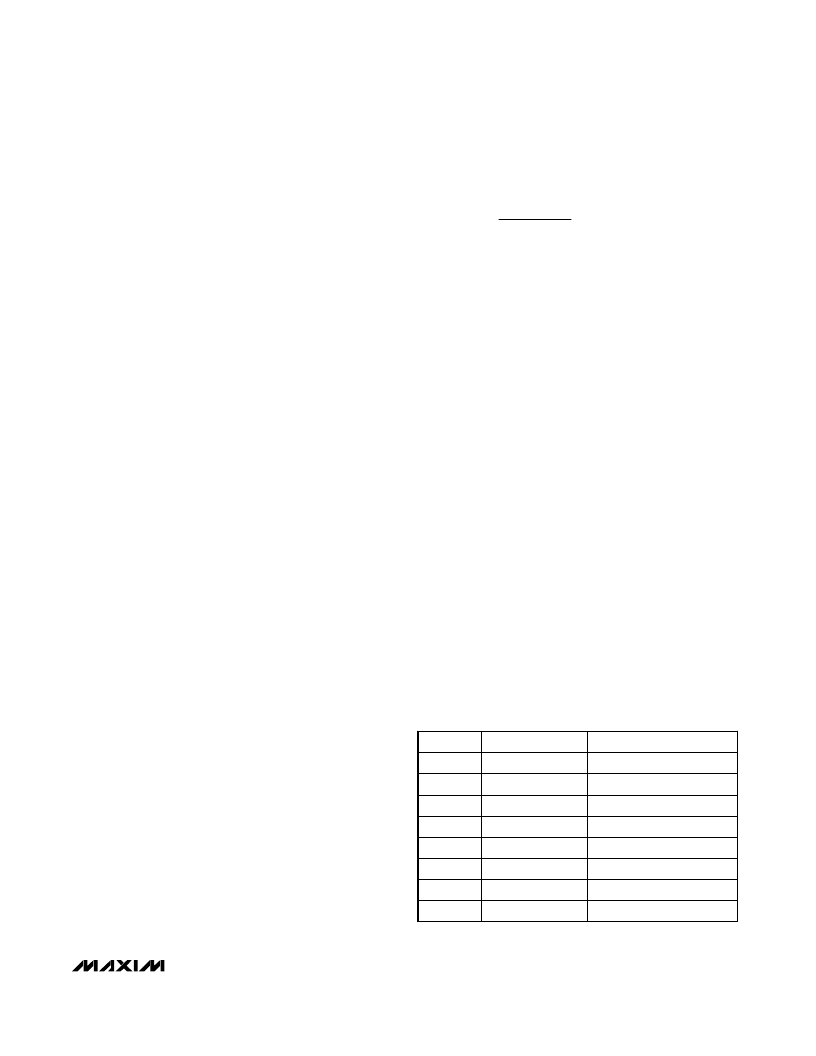
MCLK frequency. Program the sample rates with pins
S0, S1, and S2, as shown in Table 1.
C
=
M
6-Bit Quadrature Digitizer
______________________________________________________________________________________
15
S2 S1 S0
Sample Rate
Description
0 0
0
f
c
/1
Full Sample Rate
0
0
1
f
c
/2
Div–2 Sample Rate
0
1
0
f
c
/4
Div–4 Sample Rate
0
1
1
f
c
/8
Div–8 Sample Rate
1 0
0
f
c
/8
Div–8 Sample Rate
1 0
1
f
c
/16
Div–16 Sample Rate
1
1
0
f
c
/32
Div–32 Sample Rate
1
1
1
f
c
/64
Div–64 Sample Rate
Table 1. Sample-Rate Control
Note: The inputs S0, S1, and S2 are
not
latched.
相關(guān)PDF資料 |
PDF描述 |
|---|---|
| MAX2102 | 16-Bit Buffers/Drivers With 3-State Outputs 48-TVSOP -40 to 85 |
| MAX2102-MAX2105 | Direct-Conversion Tuner ICs for Digital DBS Applications |
| MAX2105 | 16-Bit Buffers/Drivers With 3-State Outputs 48-TSSOP -40 to 85 |
| MAX2105CWI | Direct-Conversion Tuner ICs for Digital DBS Applications |
| MAX2104 | 16-Bit Buffers/Drivers With 3-State Outputs 48-TSSOP -40 to 85 |
相關(guān)代理商/技術(shù)參數(shù) |
參數(shù)描述 |
|---|---|
| MAX2102 | 制造商:MAXIM 制造商全稱:Maxim Integrated Products 功能描述:Evaluation Kit |
| MAX2102/MAX2105 | 制造商:MAXIM 制造商全稱:Maxim Integrated Products 功能描述:Direct-Conversion Tuner ICs for Digital DBS Applications |
| MAX2102_1 | 制造商:MAXIM 制造商全稱:Maxim Integrated Products 功能描述:Evaluation Kit |
| MAX2102CWI | 制造商:Rochester Electronics LLC 功能描述: 制造商:Maxim Integrated Products 功能描述: |
| MAX2102CWI.B50030 | 制造商:Maxim Integrated Products 功能描述: |
發(fā)布緊急采購,3分鐘左右您將得到回復(fù)。