- 您現(xiàn)在的位置:買賣IC網(wǎng) > PDF目錄67763 > M37643F8FP 8-BIT, FLASH, 12 MHz, MICROCONTROLLER, PQFP80 PDF資料下載
參數(shù)資料
| 型號: | M37643F8FP |
| 元件分類: | 微控制器/微處理器 |
| 英文描述: | 8-BIT, FLASH, 12 MHz, MICROCONTROLLER, PQFP80 |
| 封裝: | 14 X 20 MM, 0.80 MM PITCH, PLASTIC, QFP-80 |
| 文件頁數(shù): | 46/120頁 |
| 文件大小: | 1253K |
| 代理商: | M37643F8FP |
第1頁第2頁第3頁第4頁第5頁第6頁第7頁第8頁第9頁第10頁第11頁第12頁第13頁第14頁第15頁第16頁第17頁第18頁第19頁第20頁第21頁第22頁第23頁第24頁第25頁第26頁第27頁第28頁第29頁第30頁第31頁第32頁第33頁第34頁第35頁第36頁第37頁第38頁第39頁第40頁第41頁第42頁第43頁第44頁第45頁當前第46頁第47頁第48頁第49頁第50頁第51頁第52頁第53頁第54頁第55頁第56頁第57頁第58頁第59頁第60頁第61頁第62頁第63頁第64頁第65頁第66頁第67頁第68頁第69頁第70頁第71頁第72頁第73頁第74頁第75頁第76頁第77頁第78頁第79頁第80頁第81頁第82頁第83頁第84頁第85頁第86頁第87頁第88頁第89頁第90頁第91頁第92頁第93頁第94頁第95頁第96頁第97頁第98頁第99頁第100頁第101頁第102頁第103頁第104頁第105頁第106頁第107頁第108頁第109頁第110頁第111頁第112頁第113頁第114頁第115頁第116頁第117頁第118頁第119頁第120頁
31
7643 Group
SINGLE-CHIP 8-BIT CMOS MICROCOMPUTER
MITSUBISHI MICROCOMPUTERS
PRELIMINAR
Y
Notice:
This
is not
a final
specification.
Some
parametric
limits
are
subject
to
change.
CTS (Clear-to-Send) Function
As a transmitter, the UART can be configured to recognize the
_______
Clear-to-Send (CTS) input as a handshaking signal. This is en-
abled by setting the CTS Function Enable Bit (bit 5 of UCON) to
“1”. If CTS function is enabled, even when transmission is enabled
and the UART transmit buffer register is filled with the data, the
transmission never starts; but it will start when inputting “L” to the
_______
CTS pin.
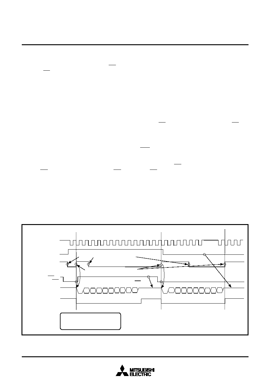
Figures 25 and 26 show the UART transmit timings.
UTXD output (P84/UTXD)
D0
D1
SP
ST
D2
D3 D4
D5 D6
D7
P
ST
SP
D0
D1
D2
D3
D4
D5
D6
D7
P
CTS pin
(P86/CTS)
Transfer clock
Tranmit enable bit
Transmit buffer
empty flag
Transmit complete flag
Data set into UART transmit buffer register 1
Data transferring from UART
transmit buffer register 1 to Transmit shift register 1
Halt due to CTS = “H”
Halt due to Tranmit
enable bit = “0”
This timing applying to the conditions:
Character length = 8 bits
Parity enabled
1 stop bit
UART Receive Operation
Reception is enabled when the Receive Enable Bit is “1”. Detec-
tion of the start bit makes transfer clocks generated and the data
reception starts in the LSB first.
When using 9-bit character length, read the received data from the
UART receive buffer register 2 (high-order byte) first before the
UART receive buffer register 1 (low-order byte).
Reception requires the following setup:
(1) Define a baud rate by setting a value n (n = 0 to 255) into
UART baud rate generator (addresses 003116).
(2) Set the Receive Initialization Bit (bit 3 of UCON) to “1”.
(3) Configure the data format and clock selection by setting the
UART mode register.
(4) Set the RTS Function Enable Bit (bit 5 of UCON) if RTS func-
tion will be used.
(5) Set the Receive Enable Bit (bit 1 of UCON) to “1”.
_______
Fig. 25 UART transmit timing (CTS function enabled)
UART Transmit Operation
Transmission starts when the Transmit Enable Bit is “1” and the
Transmit Buffer Empty Flag is “0”. Additionally, when CTS function
enabled, the CTS pin must be “L” to be started. The data in which
Start Bit and Stop Bit or Parity Bit are also added is transmitted
from the low-order byte sequentially. When using 9-bit character
length, set the data into the UART transmit buffer register 2 (high-
order byte) first before the UART transmit buffer register 1
(low-order byte).
Once the transmission starts, the Transmit Enable Bit, the Trans-
_______
mit Buffer Empty Flag and the CTS pin state (when this is
enabled) could not be checked until the transmission in progress
has ended.
Transmission requires the following setup:
(1) Define a baud rate by setting a value n (n = 0 to 255) into
UART baud rate generator (addresses 003116).
(2) Set the Transmit Initialization Bit (bit 2 of UCON) to “1”. This
will set the UART status register to “0316”.
(3) Select the interrupt source with the Transmit Interrupt Source
Select Bit (bit 4 of UCON).
(4) Configure the data format and clock selection by setting the
UART mode register.
(5) Set the CTS Function Enable Bit (bit 5 of UCON) if CTS func-
tion will be used.
(6) Set the Transmit Enable Bit (bit 0 of UCON) to “1”.
If updating a value of UART baud rate generator while the data is
being transmitted, be sure to disable the transmission before up-
dating. If the former data remains in the UART transmit buffer
registers 1 and 2 at retransmission, an undefined data might be
output.
相關PDF資料 |
PDF描述 |
|---|---|
| M37643F8HP | 8-BIT, FLASH, 12 MHz, MICROCONTROLLER, PQFP80 |
| M37643M8-XXXHP | 8-BIT, MROM, 12 MHz, MICROCONTROLLER, PQFP80 |
| M37702S1LGP | 16-BIT, 8 MHz, MICROCONTROLLER, PQFP80 |
| M37702M2LXXXGP | 16-BIT, MROM, 8 MHz, MICROCONTROLLER, PQFP80 |
| M37702M2LXXXHP | 16-BIT, MROM, 8 MHz, MICROCONTROLLER, PQFP80 |
相關代理商/技術參數(shù) |
參數(shù)描述 |
|---|---|
| M37643F8M8-XXXFP | 制造商:RENESAS 制造商全稱:Renesas Technology Corp 功能描述:SINGLE-CHIP 8-BIT CMOS MICROCOMPUTER |
| M37643M8E8-XXXFP | 制造商:RENESAS 制造商全稱:Renesas Technology Corp 功能描述:SINGLE-CHIP 8-BIT CMOS MICROCOMPUTER |
| M37643M8M8-XXXFP | 制造商:RENESAS 制造商全稱:Renesas Technology Corp 功能描述:SINGLE-CHIP 8-BIT CMOS MICROCOMPUTER |
| M3764A-12 | 制造商:OK International 功能描述: |
| M3765 | 制造商:未知廠家 制造商全稱:未知廠家 功能描述:HORN/SIREN WITH SOFT CHIRP 6 ALARM SOUNDS |
發(fā)布緊急采購,3分鐘左右您將得到回復。