- 您現(xiàn)在的位置:買賣IC網(wǎng) > PDF目錄361035 > LM9832CCVJD (NATIONAL SEMICONDUCTOR CORP) LM9832 42-Bit Color, 1200dpi USB Image Scanner PDF資料下載
參數(shù)資料
| 型號: | LM9832CCVJD |
| 廠商: | NATIONAL SEMICONDUCTOR CORP |
| 元件分類: | 消費家電 |
| 英文描述: | LM9832 42-Bit Color, 1200dpi USB Image Scanner |
| 中文描述: | SPECIALTY CONSUMER CIRCUIT, PQFP100 |
| 封裝: | PLASTIC, TQFP-100 |
| 文件頁數(shù): | 36/42頁 |
| 文件大小: | 337K |
| 代理商: | LM9832CCVJD |
第1頁第2頁第3頁第4頁第5頁第6頁第7頁第8頁第9頁第10頁第11頁第12頁第13頁第14頁第15頁第16頁第17頁第18頁第19頁第20頁第21頁第22頁第23頁第24頁第25頁第26頁第27頁第28頁第29頁第30頁第31頁第32頁第33頁第34頁第35頁當前第36頁第37頁第38頁第39頁第40頁第41頁第42頁
36
www.national.com
12.17 Turbo and Preview Modes
These modes actually existed in the LM9831, but were not docu-
mented.
The Turbo and Preview modes allow additional pixel averaging
(horizontal resolution reduction) to be done in the analog domain.
This can be useful, for example, when you have a 1200 dpi scan-
ner and wish to scan at 75 or 50dpi. The HDPI divider function’s
lowest resolution is divide-by-12. With the HDPI divider set to
divide-by-8 and turbo or preview mode set to x2, the horizontal
resolution will be 1200/16 = 75dpi. With the HDPI divider set to
divide-by-12 and turbo or preview mode set to x2, the horizontal
resolution will be 1200/24 = 50dpi. The HDPI divider and
Turbo/Preview modes can be used in any combination.
For a Preview factor of xN, the Preview Mode operates by
increasing the pixel clocks to the CCD by a factor of N, while sup-
pressing (N-1) reset pulses out of every N pixels. This is only use-
ful for CCDs (or CIS sensors made with CCD technology).
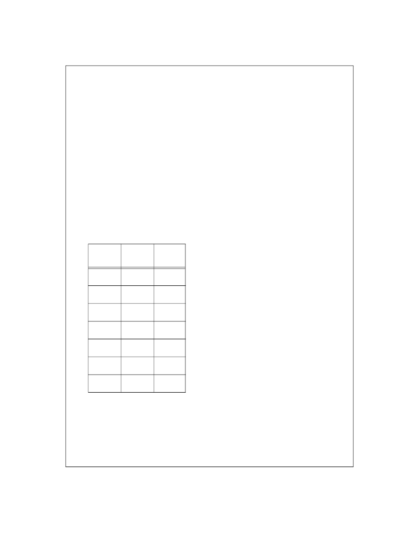
In the Turbo Mode, the entire analog front end is run N times
faster, and every N pixels are averaged together before they are
converted to digital by the ADC. When using Turbo Mode, the
range of registers 0F to 18 is reduced by the Turbo Mode factor,
according to the following table.
13.0 PORTING SOFTWARE FOR LM9830 TO LM9832
The LM9832 is similar in architecture to the LM9830. Porting a
TWAIN driver from the LM9830 to the LM9832 is relatively
straightforward if consideration is given to the following issues.
The LM9832 includes almost all the features of the LM9830, plus
several new ones. The first step is to change the LM9830 Twain
driver so that it works with the LM9832. The second step is to
take advantage of the new features of the LM9832 that will allow
you to obtain even better, faster scans than you obtained with the
LM9830.
13.1 Porting Step 1
13.1.1 Adjust for Register Changes
While more than 50% of the registers in the LM9832 are in the
same location and perform the same function as they did in the
LM9830, many other registers have changed. Sometimes the
address of a register changed, sometimes the location of the bits
inside a register were moved, some register settings were com-
bined or deleted, and the size of some registers was changed.
Please compare the register listings for the LM9830 and LM9832
carefully. This is a list of registers that have changed:
Registers 1, 2, 3, 4, 7, 9, B, 19, 1A, 1B, 3E-41, 42, 43-44, 4E-4F,
51-53, 54, 5A, 5B, 5E.
13.1.2 Choosing the MCLK Divider (Register 0x08)
The datarate coming out of the Horizontal DPI Divider must be
1.1MHz or less. If it is faster than this, the LM9832 will not oper-
ate correctly. Since the maximum USB datarate is about 1MHz,
this does not impact the performance of the scanner in any way.
This is the Clock Divider Rule:
(MCLK_divider)(HDPI_divider)(ITA) >= 6.
The ITA (Integration Time Adjust) refers to register 19, and will be
discussed in a later section. If register 19 = 0, then the value of
ITA = 1 for the purposes of this formula.
If register 19 = 0, this formula means that if the HDPI_divider = 1,
the MCLK_divider must be set to divide-by-6 (reg 08 = 10 [deci-
mal]) or higher. If the HDPI_divider = 4, the MCLK_divider must
be set to divide-by-2 (reg 08 = 2) or higher. If the HDPI_divider is
6 or larger, then the MCLK_divider can be set to divide-by-1
(reg08 = 0).
See
13.2.2 Integration Time Adjustment Function
for addi-
tional information.
13.1.3 Calibration
In the LM9830, calibration was always performed at the optical
resolution of the scanner. For example, if the optical resolution of
the scanner was 600dpi, then calibration was performed at
600dpi even if the scan was going to be at 300dpi or 150dpi.
To keep the speed of the LM9832 high while using slower DRAM
(instead of SRAM), the architecture of the LM9832 was changed
so that the Horizontal DPI adjust function is performed beforethe
pixel rate offset and shading correction, instead of after (as in the
LM9830).
This means that the calibration routine needs to be changed so
that register 9 is set to the desired scan resolution before calibra-
tion.
13.1.4 Pixel Rate Offset Correction
The LM9832 now uses 14 bits for the offset correction of each
pixel. The offset correction data is shifted up to fit into the 16 bit
DRAM. For example, offset correction codes of 3, 31 and 4096
would be transmitted to the dataport as:
Mode
Pixel Rate
Registers
0F to 18
Range
3 Channel,
Turbo off
MCLK/24
0 - 23
3 Channel,
Turbo x2
MCLK/12
0 - 11
3 Channel,
Turbo x3
MCLK/8
0 - 7
3 Channel,
Turbo x4
MCLK/6
0 - 5
3 Channel,
Turbo x6
MCLK/4
0 - 3
1 Channel,
Turbo off
MCLK/8
0 - 7
1 Channel,
Turbo x2
MCLK/4
0 - 3
Applications Information
(Continued)
L
相關PDF資料 |
PDF描述 |
|---|---|
| LM9832 | LM9832 42-Bit Color, 1200dpi USB Image Scanner |
| LM9833CCVJD | LM9833 48-Bit Color, 1200dpi USB Image Scanner |
| LM9833 | LM9833 48-Bit Color, 1200dpi USB Image Scanner |
| LM98501CCVBH | 10-Bit, 27 MSPS Camera Signal Processor |
| LM98501 | 10-Bit, 27 MSPS Camera Signal Processor |
相關代理商/技術參數(shù) |
參數(shù)描述 |
|---|---|
| LM9832CCVS-B | 制造商:Texas Instruments 功能描述: |
| LM9833 | 制造商:NSC 制造商全稱:National Semiconductor 功能描述:LM9833 48-Bit Color, 1200dpi USB Image Scanner |
| LM9833B-F WAF | 制造商:Texas Instruments 功能描述: |
| LM9833CCVJD | 制造商:Texas Instruments 功能描述:USB Image Scanner 100-Pin TQFP |
| LM9833CCVJD NOPB | 制造商:Texas Instruments 功能描述:Bulk |
發(fā)布緊急采購,3分鐘左右您將得到回復。