- 您現(xiàn)在的位置:買賣IC網(wǎng) > PDF目錄98001 > LM9617CCEA-2 (NATIONAL SEMICONDUCTOR CORP) SPECIALTY ANALOG CIRCUIT, CQCC48 PDF資料下載
參數(shù)資料
| 型號(hào): | LM9617CCEA-2 |
| 廠商: | NATIONAL SEMICONDUCTOR CORP |
| 元件分類: | 模擬信號(hào)調(diào)理 |
| 英文描述: | SPECIALTY ANALOG CIRCUIT, CQCC48 |
| 封裝: | LCC-48 |
| 文件頁(yè)數(shù): | 7/40頁(yè) |
| 文件大小: | 408K |
| 代理商: | LM9617CCEA-2 |
第1頁(yè)第2頁(yè)第3頁(yè)第4頁(yè)第5頁(yè)第6頁(yè)當(dāng)前第7頁(yè)第8頁(yè)第9頁(yè)第10頁(yè)第11頁(yè)第12頁(yè)第13頁(yè)第14頁(yè)第15頁(yè)第16頁(yè)第17頁(yè)第18頁(yè)第19頁(yè)第20頁(yè)第21頁(yè)第22頁(yè)第23頁(yè)第24頁(yè)第25頁(yè)第26頁(yè)第27頁(yè)第28頁(yè)第29頁(yè)第30頁(yè)第31頁(yè)第32頁(yè)第33頁(yè)第34頁(yè)第35頁(yè)第36頁(yè)第37頁(yè)第38頁(yè)第39頁(yè)第40頁(yè)
Confidential
15
www.national.com
Functional Description (continued)
6.0
CLOCK GENERATION MODULE
The LM9617 contains a clock generation module that will create
two clocks as follows:
Hclk,
the horizontal clock. This is an internal system
clock and can be programmed to be the input
clock (mclk) or mclk divided by any number
between 1 and 255.
CLKpixel the pixel clock. This is the external pixel clock
that appears at the digital video port. It can be
Hclk or Hclk divided by 2. This clock cannot be
programed.
7.0
FRAME RATE PROGRAMING
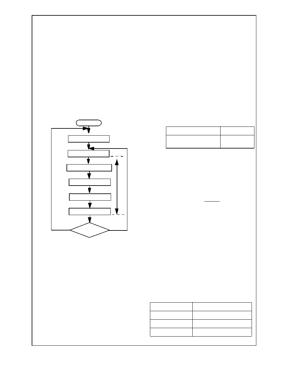
A frame is defined as the time it takes to reset every pixel in the
array, integrate the incident light, convert it to digital data and
present it on the digital video port. This is not a concurrent pro-
cess and is characterized in a series of events each needing a
certain amount of time as shown in Figure 23.
Figure 23. Frame Readout Flow Diagram
7.1
Full Frame Integration
Full frame integration is when each pixel in the array integrates
light incident on it for the duration of a frame (see Figure 24).
The number of Hclk clock cycles required to process & shift out
one row of pixels is given by:
Where:
Ropcycle
is a fixed integer value of 780 representing the
Row Operation Cycle Time in multiples of Hclk
clock cycles. It is the time required to carry out
all fixed row operations outlined in Figure 23.
Rdelay
a programmable value between 0 & 2047 repre-
senting the Row Delay Time in multiples of Hclk.
This parameter allows the Row Operation Cycle
time to be extended. (See the Row Delay High
and Row Delay Low registers).
The number of rows in a scan window is given by:
Where:
RADend
is the end row address of the defined scan win-
dow. (See section 2.1)
RADstart is the start row address of the defined scan win-
dow. (Scan section 2.1).
The number of Hclk clocks required to process a full frame is
given by:
Where:
Mfactor
is a Mode Factor which must be applied. It is
dependent on the selected mode of operation as
shown in the table below:
SWN
rows is the Number of Rows in Selected Scan Win-
dow.
Fdelay
a programmable value between 0 & 4097 repre-
senting the Inter Frame Delay in multiples of
RNHclk. This parameter allows the frame time to
be extended. (See the Frame Delay High and
Frame Delay Low registers).
The frame rate is given by:
7.2
Partial Frame Integration
In some cases it is desirable to reduce the time during which the
pixels in the array are allowed to integrate incident light without
changing the frame rate.
This is known as Partial Fame Integration and can be achieved
by resetting pixels in a given row ahead of the row being
selected for readout as shown in Figure 24. The number of Hclk
clocks required to process a partial frame is given by:
Where:
RN
Hclk
is the number of Hclk clock cycles required to
process & shift out one row of pixels.
Itime
is the number of rows ahead of the current row
to be reset. (See the Integration Time High and
Low registers).
The Integration time is subject to the following limits:
Start
Row address = 0
Row delay time
Transfer all pixels to CDS
Shift all pixels out of row
Row address + 1
Last row?
Reset all pixels in row
Yes
No
R
o
w
T
im
e
RNHclk = Ropcycle + Rdelay
Progressive Scan
1
Sub-sampling or Interlace/
Interlace
0.5
Mode
Limit
Progressive Scan
Itime <= SWNrows + Fdelay
Interlace
Itime <= SWNrows + 2*Fdelay
Sub-Sampled
Itime <= SWNrows + 0.5*Fdelay
SWNrows = (RADend - RADstart) + 1
FNHclk = [(Mfactor * SWNrows) + Fdelay ] * RNHclk
Hclk
FN
Hclk
Frame Rate =
FP
Hclk = RNHclk * Itime
L
M
9
6
1
7
相關(guān)PDF資料 |
PDF描述 |
|---|---|
| LM96194CIAQX | 9-CHANNEL POWER SUPPLY SUPPORT CKT, QCC48 |
| LM98725 | SPECIALTY ANALOG CIRCUIT, PDSO56 |
| LMD18245MWC | STEPPER MOTOR CONTROLLER, 6 A, UUC |
| LMX1601TMX/NOPB | PLL FREQUENCY SYNTHESIZER, 1100 MHz, PDSO16 |
| LMX1600TMX/NOPB | PLL FREQUENCY SYNTHESIZER, 2000 MHz, PDSO16 |
相關(guān)代理商/技術(shù)參數(shù) |
參數(shù)描述 |
|---|---|
| LM9618 | 制造商:NSC 制造商全稱:National Semiconductor 功能描述:Monochrome CMOS Image Sensor VGA 30 FPS |
| LM96194 | 制造商:NSC 制造商全稱:National Semiconductor 功能描述:TruTherm⑩ Hardware Monitor with PI Fan Control for Workstation Management |
| LM96194CISQ | 功能描述:板上安裝溫度傳感器 RoHS:否 制造商:Omron Electronics 輸出類型:Digital 配置: 準(zhǔn)確性:+/- 1.5 C, +/- 3 C 溫度閾值: 數(shù)字輸出 - 總線接口:2-Wire, I2C, SMBus 電源電壓-最大:5.5 V 電源電壓-最小:4.5 V 最大工作溫度:+ 50 C 最小工作溫度:0 C 關(guān)閉: 安裝風(fēng)格: 封裝 / 箱體: 設(shè)備功能:Temperature and Humidity Sensor |
| LM96194CISQ/NOPB | 功能描述:板上安裝溫度傳感器 RoHS:否 制造商:Omron Electronics 輸出類型:Digital 配置: 準(zhǔn)確性:+/- 1.5 C, +/- 3 C 溫度閾值: 數(shù)字輸出 - 總線接口:2-Wire, I2C, SMBus 電源電壓-最大:5.5 V 電源電壓-最小:4.5 V 最大工作溫度:+ 50 C 最小工作溫度:0 C 關(guān)閉: 安裝風(fēng)格: 封裝 / 箱體: 設(shè)備功能:Temperature and Humidity Sensor |
| LM96194CISQX | 功能描述:板上安裝溫度傳感器 RoHS:否 制造商:Omron Electronics 輸出類型:Digital 配置: 準(zhǔn)確性:+/- 1.5 C, +/- 3 C 溫度閾值: 數(shù)字輸出 - 總線接口:2-Wire, I2C, SMBus 電源電壓-最大:5.5 V 電源電壓-最小:4.5 V 最大工作溫度:+ 50 C 最小工作溫度:0 C 關(guān)閉: 安裝風(fēng)格: 封裝 / 箱體: 設(shè)備功能:Temperature and Humidity Sensor |
發(fā)布緊急采購(gòu),3分鐘左右您將得到回復(fù)。