- 您現(xiàn)在的位置:買賣IC網(wǎng) > PDF目錄377624 > LF3320QC15 (LOGIC DEVICES INC) Horizontal Digital Image Filter PDF資料下載
參數(shù)資料
| 型號: | LF3320QC15 |
| 廠商: | LOGIC DEVICES INC |
| 元件分類: | 數(shù)字信號處理外設(shè) |
| 英文描述: | Horizontal Digital Image Filter |
| 中文描述: | 12-BIT, DSP-DIGITAL FILTER, PQFP144 |
| 封裝: | PLASTIC, QFP-144 |
| 文件頁數(shù): | 5/24頁 |
| 文件大小: | 575K |
| 代理商: | LF3320QC15 |
DEVICES INCORPORATED
Video Imaging Products
2-5
LF3320
Horizontal Digital Image Filter
08/16/2000
–
LDS.3320-N
Registers on the rising edge of CLK.
When SHENB is HIGH, data can not be
loaded into the Cascade Registers or
shifted through the I/ D Registers and
their contents will not be changed.
In Single Filter Mode, SHENB also
enables or disables the loading of data
into the Input (DIN
11-0
), Reverse
Cascade Output (ROUT
11-0
) and Filter
A I/ D Registers. It is important to note
that in Single Filter Mode, both
SHENA and SHENB should be
connected together. Both must be
active to enable data loading in Single
Filter Mode. SHENB is latched on the
rising edge of CLK.
RSLA
3-0
— Filter A Round/Select/Limit
Control
RSLA
3-0
determines which of the
sixteen user-programmable Round/
Select/ Limit registers (RSL registers)
are used in the Filter A RSL circuitry.
A value of 0 on RSLA
3-0
selects RSL
register 0. A value of 1 selects RSL
register 1 and so on. RSLA
3-0
is
latched on the rising edge of CLK (see
the round, select, and limit sections for
a complete discussion).
RSLB
3-0
— Filter B Round/Select/Limit
Control
RSLB
3-0
determines which of the sixteen
user-programmable RSL registers are
used in the Filter B RSL circuitry. A
value of 0 on RSLB
3-0
selects RSL
register 0. A value of 1 selects RSL
register 1 and so on. RSLB
3-0
is latched
on the rising edge of CLK (see the round,
select, and limit sections for a complete
discussion).
OED — DOUT Output Enable
When OED is LOW, DOUT
15-0
is
enabled for output. When OED is
HIGH, DOUT
15-0
is placed in a high-
impedance state.
OEC — COUT/ROUT Output Enable
When OEC is LOW, COUT
11-0
and
ROUT
3-0
are enabled for output. When
OEC is HIGH, COUT
11-0
and ROUT
3-0
are placed in a high-impedance state.
PAUSEA — LF Interface
TM
Pause
When PAUSEA is HIGH, the Filter A
LF Interface
TM
loading sequence is
halted until PAUSEA is returned to a
LOW state. This effectively allows the
user to load coefficients and control
registers at a slower rate than the
master clock (see the LF Interface
TM
section for a full discussion).
PAUSEB — LF Interface
TM
Pause
When PAUSEB is HIGH, the Filter B LF
Interface
TM
loading sequence is halted
until PAUSEB is returned to a LOW
state. This effectively allows the user
to load coefficients and control regis-
ters at a slower rate than the master
clock (see the LF Interface
TM
section for
a full discussion).
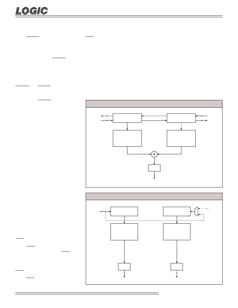
F
IGURE
4. S
INGLE
F
ILTER
M
ODE
DIN
11-0
I/D
REGISTERS
FILTER
A
RSL
CIRCUIT
FILTER
B
ROUT
11-0
COUT
11-0
DOUT
15-0
I/D
REGISTERS
12
12
12
16
RIN
11-0
12
DIN
11-0
I/D
REGISTERS
FILTER
A
FILTER
B
DOUT
15-0
I/D
REGISTERS
R.S.L.
CIRCUIT
R.S.L.
CIRCUIT
12
16
ROUT
3-0
/ COUT
11-0
16
RIN
11-0
12
F
IGURE
5. D
UAL
F
ILTER
M
ODE
相關(guān)PDF資料 |
PDF描述 |
|---|---|
| LF3330 | Vertical Digital Image Filter(垂直數(shù)字圖像濾波器) |
| LF3338 | 8-Bit Vertical Digital Image Filter(8位垂直數(shù)字圖像濾波器) |
| LF3338QC12 | 8-Bit Vertical Digital Image Filter |
| LF3347 | High-Speed Image Filter with Coefficient RAM(高速圖像濾波器(帶系數(shù)RAM)) |
| LF3347QC12 | CAP 1.0UF 63V METAL POLY |
相關(guān)代理商/技術(shù)參數(shù) |
參數(shù)描述 |
|---|---|
| LF3320QC18 | 制造商:未知廠家 制造商全稱:未知廠家 功能描述:Digital Filter |
| LF3320QC25 | 制造商:未知廠家 制造商全稱:未知廠家 功能描述:Digital Filter |
| LF3321 | 制造商:LOGIC 制造商全稱:LOGIC 功能描述:Horizontal Digital Image Filter Improved Performance |
| LF3330 | 制造商:LOGIC 制造商全稱:LOGIC 功能描述:Vertical Digital Image Filter |
| LF3330FMB12 | 制造商:未知廠家 制造商全稱:未知廠家 功能描述:Digital Filter |
發(fā)布緊急采購,3分鐘左右您將得到回復(fù)。