- 您現在的位置:買賣IC網 > PDF目錄377624 > LF3320QC15 (LOGIC DEVICES INC) Horizontal Digital Image Filter PDF資料下載
參數資料
| 型號: | LF3320QC15 |
| 廠商: | LOGIC DEVICES INC |
| 元件分類: | 數字信號處理外設 |
| 英文描述: | Horizontal Digital Image Filter |
| 中文描述: | 12-BIT, DSP-DIGITAL FILTER, PQFP144 |
| 封裝: | PLASTIC, QFP-144 |
| 文件頁數: | 3/24頁 |
| 文件大小: | 575K |
| 代理商: | LF3320QC15 |
DEVICES INCORPORATED
Video Imaging Products
2-3
LF3320
Horizontal Digital Image Filter
08/16/2000
–
LDS.3320-N
SIGNAL DEFINITIONS
Power
V
CC
and GND
+3.3 V power supply. All pins must be
connected.
Clock
CLK — Master Clock
The rising edge of CLK strobes all
enabled registers.
Inputs
DIN
11-0
— Data Input
DIN
11-0
is the 12-bit data input port to
Filter A. In Dual Filter Mode, DIN
11-0
can also be the 12-bit input port to
Filter B. Data is latched on the rising
edge of CLK.
RIN
11-0
— Reverse Cascade Input
In Single Filter Mode, RIN
11-0
is the 12-
bit reverse cascade input port. This
port is connected to ROUT
11-0
of
another LF3320. In Dual Filter Mode,
RIN
11-0
can be the 12-bit input port to
Filter B. Data is latched on the rising
edge of CLK.
CFA
11-0
— Coefficient A Input
CFA
11-0
is used to load data into the
Filter A coefficient banks (banks 0
through 7) and the configuration/
control registers. Data present on
CFA
11-0
is latched into the Filter A LF
Interface
TM
on the rising edge of CLK
when LDA is LOW (see the LF
Interface
TM
section for a full discus-
sion).
CAA
7-0
— Coefficient Address A
CAA
7-0
determines which row of data
in coefficient banks 0 through 7 is fed
to the multipliers. CAA
7-0
is latched
into Coefficient Address Register A on
the rising edge of CLK when CENA is
LOW.
CFB
11-0
— Coefficient B Input
CFB
11-0
is used to load data into the
Filter B coefficient banks (banks 8
through 15) and the configuration/
control registers. Data present on
CFB
11-0
is latched into the Filter B LF
Interface
TM
on the rising edge of CLK
when LDB is LOW (see the LF
Interface
TM
section for a full discussion).
CAB
7-0
— Coefficient Address B
CAB
7-0
determines which row of data in
coefficient banks 8 through 15 is fed to the
multipliers. CAB
7-0
is latched into
Coefficient Address Register B on the
rising edge of CLK when CENB is LOW.
Outputs
DOUT
15-0
— Data Output
DOUT
15-0
is the 16-bit registered data
output port for the overall filter (Single
Filter Mode) or Filter A (Dual Filter
Mode).
COUT
11-0
— Cascade Output
In Single Filter Mode, COUT
11-0
is a
12-bit registered cascade output port.
COUT
11-0
should be connected to
DIN
11-0
of another LF3320. In Dual
Filter Mode, COUT
11-0
is a 12-bit
registered output port for the lower
twelve bits of the 16-bit Filter B output.
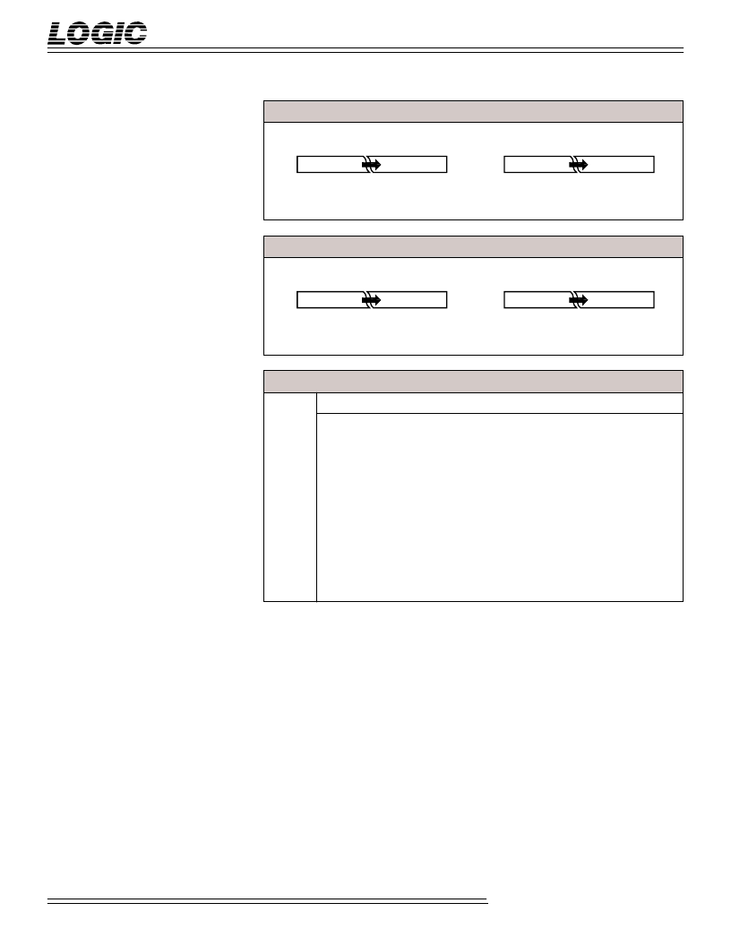
F
IGURE
2.
I
NPUT
F
ORMATS
11 10 9
–
2
11
(Sign)
2
2
2
1
2
1
0
2
0
2
10
2
9
11 10 9
–
2
0
(Sign)
2
1
0
2
–
1
2
–
2
2
–
9
2
–
10
2
–
11
Input Data
Coefficient Data
T
ABLE
1.
O
UTPUT
F
ORMATS
SLCT
4-0
S
15
S
14
S
13
·
·
·
·
·
·
·
·
·
·
·
·
S
8
S
7
·
·
·
·
·
·
·
·
·
·
·
·
S
2
S
1
S
0
00000
F
15
F
14
F
13
F
8
F
7
F
2
F
1
F
0
00001
F
16
F
15
F
14
F
9
F
8
F
3
F
2
F
1
00010
·
·
·
F
17
·
·
·
F
16
·
·
·
F
15
·
·
·
F
10
·
·
·
F
9
·
·
·
F
4
·
·
·
F
3
·
·
·
F
2
·
·
·
01110
F
29
F
28
F
27
·
·
·
·
·
·
·
·
·
F
22
F
21
·
·
·
·
·
·
·
·
·
F
16
F
15
F
14
01111
F
30
F
29
F
28
F
23
F
22
F
17
F
16
F
15
10000
F
31
F
30
F
29
F
24
F
23
F
18
F
17
F
16
F
IGURE
3.
A
CCUMULATOR
O
UTPUT
F
ORMATS
31 30 29
–
2
20
(Sign)
2
1
0
2
19
2
18
2
–
9
2
–
10
2
–
11
31 30 29
–
2
20
(Sign)
2
1
0
2
19
2
18
2
–
9
2
–
10
2
–
11
Accumulator A Output
Accumulator B Output
相關PDF資料 |
PDF描述 |
|---|---|
| LF3330 | Vertical Digital Image Filter(垂直數字圖像濾波器) |
| LF3338 | 8-Bit Vertical Digital Image Filter(8位垂直數字圖像濾波器) |
| LF3338QC12 | 8-Bit Vertical Digital Image Filter |
| LF3347 | High-Speed Image Filter with Coefficient RAM(高速圖像濾波器(帶系數RAM)) |
| LF3347QC12 | CAP 1.0UF 63V METAL POLY |
相關代理商/技術參數 |
參數描述 |
|---|---|
| LF3320QC18 | 制造商:未知廠家 制造商全稱:未知廠家 功能描述:Digital Filter |
| LF3320QC25 | 制造商:未知廠家 制造商全稱:未知廠家 功能描述:Digital Filter |
| LF3321 | 制造商:LOGIC 制造商全稱:LOGIC 功能描述:Horizontal Digital Image Filter Improved Performance |
| LF3330 | 制造商:LOGIC 制造商全稱:LOGIC 功能描述:Vertical Digital Image Filter |
| LF3330FMB12 | 制造商:未知廠家 制造商全稱:未知廠家 功能描述:Digital Filter |
發(fā)布緊急采購,3分鐘左右您將得到回復。