- 您現(xiàn)在的位置:買賣IC網(wǎng) > PDF目錄383236 > L6260 (意法半導(dǎo)體) 4.5 - 5.5V DISK DRIVER SPINDLE & VCM, POWER & CONTROL COMBO’S PDF資料下載
參數(shù)資料
| 型號(hào): | L6260 |
| 廠商: | 意法半導(dǎo)體 |
| 英文描述: | 4.5 - 5.5V DISK DRIVER SPINDLE & VCM, POWER & CONTROL COMBO’S |
| 中文描述: | 4.5 - 5.5V的磁盤驅(qū)動(dòng)程序主軸 |
| 文件頁(yè)數(shù): | 23/30頁(yè) |
| 文件大?。?/td> | 305K |
| 代理商: | L6260 |
第1頁(yè)第2頁(yè)第3頁(yè)第4頁(yè)第5頁(yè)第6頁(yè)第7頁(yè)第8頁(yè)第9頁(yè)第10頁(yè)第11頁(yè)第12頁(yè)第13頁(yè)第14頁(yè)第15頁(yè)第16頁(yè)第17頁(yè)第18頁(yè)第19頁(yè)第20頁(yè)第21頁(yè)第22頁(yè)當(dāng)前第23頁(yè)第24頁(yè)第25頁(yè)第26頁(yè)第27頁(yè)第28頁(yè)第29頁(yè)第30頁(yè)
Example
Assuming that your motor requires 200mA run
current then the sense current would be 200/500
= 400
μ
A. Therefore for 1 volt at the sense pin a
2500 Ohm resistor is required (R = 1/400
μ
A).
Also assuming you require 1 Amp start-up cur-
rent. You need to change the sense range to 5X.
This also gives1A/2500 = 400
μ
A or 1V on a 2500
Ohm resistor.
In the normal ”at-speed” running the voltage at
this pin will vary between 0 and 2 volts approxi-
mately (e.g. when using the FLL).When using the
spindle DAC the voltage swing is from 0 to 1.25
Volts
Using the Spindle DAC for Start-Up
When the SPEED bit in the System Control Reg-
ister A (Register 3.9) is set (to 1), the speed con-
trol is given to the DAC (i.e. control is removed
from the FLL). The normal method of start-up is
achieved using the DAC rather than the FLL.
However the FLL can be used from zero speed
with an align-and-goalgorithm but start-up will be
slower. The 8-bit DAC gives 4.88mV per step with
a maximumvoltageof 1.25V.
Start-Upexample
Assume that one needs 1A max. start current and
expects a runningcurrent of 200mA.
For startup, one would program the SFETGAIN
bit to 0 and the SPEED bit to 1. With this value,
1A spindlecurrent resultsin 1A/3000, or 333
μ
A at
the SPN_I_SNS pin. Using a 3300
resistor and
programming the Spindle DAC to 1V results in the
desired 1A startupcurrent.
The startup algorithm is implemented by writing
into the Spindle Control Register A.
Once running speed is attained, the AT_SPEED
bit (System Status Register, bit 7) will go to a 1.
The CPU then sets the SFETGAIN bit to 1 and
the SPEED bit to 1. The normal running current
of 200mA again results in 200mA/600, or 333
μ
A
at the SPN_I_SNS pin. The FLL will regulate the
speedwith a npminal value of 1V.
During ”DAC control” the FLL change pump ca-
pacitor is shorted to the Spindle DAC voltage..
This allows for a smoother transition from DAC to
FLL control.
Power Devices
When S_BIPLOAR (internal) is turned on and
saturated when the spindle driver is placed in
unipolarmode and has an Rdson of 1 Ohm (worst
case over temperature). To support retract with-
out requiring an isolation diode the transistor is
designed so as not to conduct current from
source to drain even if the supplies Vp and Vdd
are at ground and the source is at a positive volt-
age.
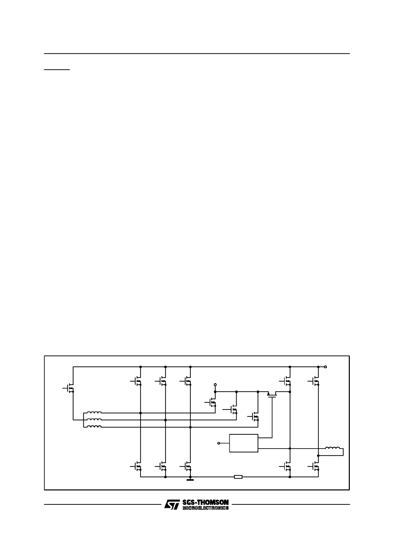
S_A_U, S_B_U and S_C_Uare the upper spindle
drive transistors. They are active whenever the
drive is in bipolar mode and can be turned on in
pairs in tripolar mode. To support retract without
requiring an isolation diode these transistors are
designed so as to not conduct current from
source to drain even if the supplies Vdd and Vp
are at ground and the source is at a positive volt-
age.
S_A_L, S_B_L and S_C_L are the lower spindle
drive transistors. They are active in unipolar,bipo-
lar and tripolar drive. In linear mode the active
transistor’s gate drive is controlled so as to bring
the current in the motor to the level set by the
speed control compensation circuit or the current
SPINDLE MOTOR
B-POLAR
PHASE A
PHASE B
PHASE C
CENTER TAP
S-A-U
S-B-U
S-C-U
S-A-L
S-B-L
S-C-L
VCM-A-U
VCM-B-U
VCM-A-L
VCM-B-L
SR-A
SR-B
SR-C
VRECT
VDD
VCM
PARK
CONTROL
VPARK
D94IN100
Figure 11.
L6260
23/30
相關(guān)PDF資料 |
PDF描述 |
|---|---|
| L6268 | 12V DISK DRIVE SPINDLE & VCM, POWER & CONTROL “COMBO” |
| L6269 | 12V DISK DRIVE SPINDLE & VCM, POWER & CONTROL “COMBO” |
| L6270 | MILLI-ACTUATOR DRIVER |
| L6271 | MILLI-ACTUATOR DRIVER |
| L6275 | 5V DISK DRIVE SPINDLE & VCM, POWER & CONTROL “COMBO” |
相關(guān)代理商/技術(shù)參數(shù) |
參數(shù)描述 |
|---|---|
| L6261 | 制造商:未知廠家 制造商全稱:未知廠家 功能描述:Servo/Spindle Motor Controller/Driver |
| L62622.6 | 制造商:STMicroelectronics 功能描述: |
| L6268 | 制造商:STMICROELECTRONICS 制造商全稱:STMicroelectronics 功能描述:12V DISK DRIVE SPINDLE & VCM, POWER & CONTROL “COMBO” |
| L6269 | 制造商:STMicroelectronics 功能描述:L6269 - Trays |
| L6269TR | 制造商:STMicroelectronics 功能描述:12V SMART POWER COMBO - Tape and Reel |
發(fā)布緊急采購(gòu),3分鐘左右您將得到回復(fù)。