- 您現(xiàn)在的位置:買賣IC網(wǎng) > PDF目錄360867 > INTEL740 64-Bit Graphics (GUI) Accelerator PDF資料下載
參數(shù)資料
| 型號: | INTEL740 |
| 英文描述: | 64-Bit Graphics (GUI) Accelerator |
| 中文描述: | 64位圖形(GUI)的加速器 |
| 文件頁數(shù): | 20/41頁 |
| 文件大小: | 435K |
| 代理商: | INTEL740 |
第1頁第2頁第3頁第4頁第5頁第6頁第7頁第8頁第9頁第10頁第11頁第12頁第13頁第14頁第15頁第16頁第17頁第18頁第19頁當(dāng)前第20頁第21頁第22頁第23頁第24頁第25頁第26頁第27頁第28頁第29頁第30頁第31頁第32頁第33頁第34頁第35頁第36頁第37頁第38頁第39頁第40頁第41頁

Intel387
TM
DX MATH COPROCESSOR
3.1.1 Intel386
TM
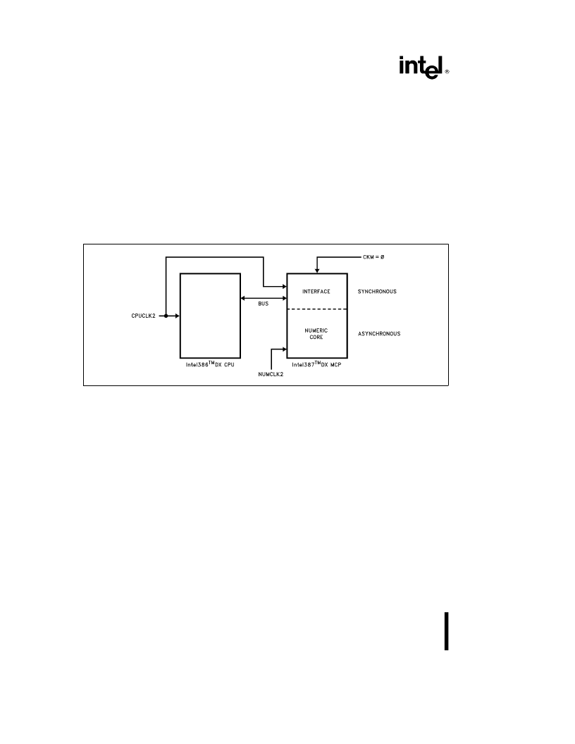
DX CPU CLOCK 2 (CPUCLK2)
This input uses the Intel386 DX CPU CLK2 signal to
time the bus control logic. Several other MCP sig-
nals are referenced to the rising edge of this signal.
When CKM
e
1 (synchronous mode) this pin also
clocks the data interface and control unit and the
floating-point unit of the MCP. This pin requires
MOS-level input. The signal on this pin is divided by
two to produce the internal clock signal CLK.
3.1.2 Intel387
TM
DX MCP CLOCK 2 (NUMCLK2)
When CKM
e
0 (asynchronous mode) this pin pro-
vides the clock for the data interface and control unit
and the floating-point unit of the MCP. In this case,
the ratio of the frequency of NUMCLK2 to the fre-
quency of CPUCLK2 must lie within the range 10:16
to 14:10. When CKM
e
1 (synchronous mode) this
pin is ignored; CPUCLK2 is used instead for the data
interface and control unit and the floating-point unit.
This pin requires TTL-level input.
3.1.3 Intel387
TM
DX MCP CLOCKING MODE
(CKM)
This pin is a strapping option. When it is strapped to
V
CC
, the MCP operates in synchronous mode; when
strapped to V
SS
, the MCP operates in asynchronous
mode. These modes relate to clocking of the data
interface and control unit and the floating-point unit
only; the bus control logic always operates synchro-
nously with respect to the Intel386 DX Microproces-
sor.
240448–7
Figure 3.2. Asynchronous Operation
20
20
相關(guān)PDF資料 |
PDF描述 |
|---|---|
| INTRO_TO_TRANSISTOR | |
| INTRUMENT | For EM60000 series |
| IO100VXI | |
| IO110VXI | |
| IO120VXI | |
相關(guān)代理商/技術(shù)參數(shù) |
參數(shù)描述 |
|---|---|
| INTEL82801 | 制造商:INTEL 制造商全稱:Intel Corporation 功能描述:82801AB (ICH0) I/O Controller Hub |
| INTEL82802AB | 制造商:INTEL 制造商全稱:Intel Corporation 功能描述:Firmware Hub (FWH) |
| INTELLIGENT CHARGER + 4AA | 制造商:Energizer 功能描述:Bulk |
| INTELLI-INCH-LR-STARTER K | 制造商:ALL MOTION 功能描述:Intelli-Inch Stepper & Controller Starter Kit |
| INTELLIPANEL | 制造商:GJD 功能描述:EXTENSION LEAD 8GANG INTELLIPANEL 制造商:GJD 功能描述:EXTENSION LEAD, 8GANG, INTELLIPANEL |
發(fā)布緊急采購,3分鐘左右您將得到回復(fù)。