- 您現(xiàn)在的位置:買賣IC網(wǎng) > PDF目錄377495 > IMC016FLSG (INTEL CORP) 5 V Series 200 Flash Memory Card(5V系列200閃速存儲(chǔ)器插卡) PDF資料下載
參數(shù)資料
| 型號(hào): | IMC016FLSG |
| 廠商: | INTEL CORP |
| 元件分類: | DRAM |
| 英文描述: | 5 V Series 200 Flash Memory Card(5V系列200閃速存儲(chǔ)器插卡) |
| 中文描述: | 16M X 8 FLASH 5V PROM CARD, 200 ns, XMA68 |
| 封裝: | PC CARD |
| 文件頁數(shù): | 17/35頁 |
| 文件大小: | 217K |
| 代理商: | IMC016FLSG |
第1頁第2頁第3頁第4頁第5頁第6頁第7頁第8頁第9頁第10頁第11頁第12頁第13頁第14頁第15頁第16頁當(dāng)前第17頁第18頁第19頁第20頁第21頁第22頁第23頁第24頁第25頁第26頁第27頁第28頁第29頁第30頁第31頁第32頁第33頁第34頁第35頁
E
iMC008/016/024/032/048/064FLSG
17
PRELIMINARY
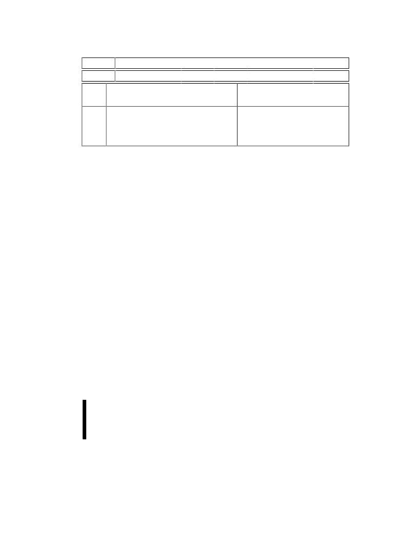
Table 7. eXtended Status Register Definitions
WBS
Reserved
bit 7
bits 6
–0
High Z
When
Busy
Status Register Bits
NOTES:
No
Yes
XSR.7 = WRITE BUFFER STATUS
1 = Write buffer available
0 = Write buffer not available
XSR.6
–XSR.0
ENHANCEMENTS
=
RESERVED FOR FUTURE
After a Buffer-Write command, XSR.7 = 1
indicates that a Write Buffer is available.
SR.6–SR.0 are reserved for future use and
should be masked when polling the status
register.
5.1.5
BLOCK ERASE COMMAND
Erase is executed one block at a time and initiated
by a two-cycle command. A block erase setup is
first written, followed by an block erase confirm.
This command sequence requires an appropriate
address within the block to be erased (erase
changes
all
block
data
preconditioning, erase, and verify are handled
internally by the WSM (invisible to the system).
After the two-cycle block erase sequence is written,
the device automatically outputs status register
data when read. The CPU can detect block erase
completion by analyzing the logic level of the STS
pin or status register bit SR.7.
Toggle OE#, CE
1
# or
CE
2
# to update the status register.
to
FFH).
Block
When the block erase is complete, status register
bit SR.5 should be checked. If a block erase error is
detected, the status register should be cleared
before system software attempts corrective actions.
The CUI remains in read status register mode until
a new command is issued.
This two-step command sequence of set-up
followed by execution ensures that block contents
are not accidentally erased. An invalid Block Erase
command sequence will result in both status
register bits SR.4 and SR.5 being set to “1.”
Successful
block
erase
corresponding block lock-bit be cleared. If block
erase is attempted when the corresponding block
lock-bit is set, SR.1 and SR.5 will be set to “1.”
requires
that
the
5.1.6
BLOCK ERASE SUSPEND COMMAND
The Block Erase Suspend command allows block-
erase interruption to read or write data in another
block of memory. Once the block erase process
starts, writing the Block Erase Suspend command
requests that the WSM suspend the block erase
sequence at a predetermined point in the algorithm.
The device outputs status register data when read
after the Block Erase Suspend command is written.
Polling status register bit SR.7 then SR.6 can
determine when the block erase operation has been
suspended (both will be set to “1”). The BUSY#
output will also transition to V
OH
. Specification
t
WHRH
defines the block erase suspend latency.
At this point, a Read Array command can be written
in order to read data from blocks other than that
which is suspended. A word-write or write-to-buffer
command sequence can also be issued during
erase suspend to write data in other blocks. During
a write operation with block erase suspended,
status register bit SR.7 will return to “0” and the
BUSY# output will transition to V
OL
.
The only other valid commands while block erase is
suspended are Read Query, Read Status Register,
Clear Status Register, Configure, and Block Erase
Resume. After a Block Erase Resume command is
written to the flash memory, the WSM will continue
the block erase process. Status register bits SR.6
and SR.7 will automatically clear and the BUSY#
output will return to V
OL
. After the Erase Resume
command is written, the device automatically
outputs status register data when read. Block erase
cannot resume until write operations initiated during
block erase suspend have completed.
相關(guān)PDF資料 |
PDF描述 |
|---|---|
| IMC024FLSG | 5 V Series 200 Flash Memory Card(5V系列200閃速存儲(chǔ)器插卡) |
| IMC064FLSG | 5 V Series 200 Flash Memory Card(5V系列200閃速存儲(chǔ)器插卡) |
| IMC032FLSG | 5 V Series 200 Flash Memory Card(5V系列200閃速存儲(chǔ)器插卡) |
| IMC048FLSG | 5 V Series 200 Flash Memory Card(5V系列200閃速存儲(chǔ)器插卡) |
| Intel Celeron Processor | Intel Celeron Processor Mobile Module MMC-2 at 400 MHz, 366 MHz, 333 MHz, and 300 MHz(工作頻率400,366,333,300和266兆赫茲帶移動(dòng)模塊和連接器2處理器) |
相關(guān)代理商/技術(shù)參數(shù) |
參數(shù)描述 |
|---|---|
| IMC01GR | 制造商:MA-COM 制造商全稱:M/A-COM Technology Solutions, Inc. 功能描述:IM Series Signal Relays |
| IMC01TS | 制造商:MA-COM 制造商全稱:M/A-COM Technology Solutions, Inc. 功能描述:IM Series Signal Relays |
| IMC02 | 制造商:TE Connectivity 功能描述:PROTECTIVE CABLE CLIP CLIP-ON 制造商:TE Connectivity 功能描述:IMC MARKER CLIP SIZE 02 |
| IMC020FLSA | 制造商:INTEL 制造商全稱:Intel Corporation 功能描述:SERIES 2 FLASH MEMORY CARDS iMC002FLSA, iMC004FLSA, iMC010FLSA, iMC020FLSA |
| IMC020FLSAET | 制造商:未知廠家 制造商全稱:未知廠家 功能描述:x8/x16 Flash EEPROM Module |
發(fā)布緊急采購,3分鐘左右您將得到回復(fù)。