- 您現(xiàn)在的位置:買賣IC網(wǎng) > PDF目錄370738 > HY29LV400 4M(X8/X16)|3.0V|55|NOR FLASH - 4M PDF資料下載
參數(shù)資料
| 型號(hào): | HY29LV400 |
| 英文描述: | 4M(X8/X16)|3.0V|55|NOR FLASH - 4M |
| 中文描述: | 4分(X8/X16)| 3.0V | 55 | NOR閃存- 4分 |
| 文件頁(yè)數(shù): | 11/40頁(yè) |
| 文件大?。?/td> | 550K |
| 代理商: | HY29LV400 |
第1頁(yè)第2頁(yè)第3頁(yè)第4頁(yè)第5頁(yè)第6頁(yè)第7頁(yè)第8頁(yè)第9頁(yè)第10頁(yè)當(dāng)前第11頁(yè)第12頁(yè)第13頁(yè)第14頁(yè)第15頁(yè)第16頁(yè)第17頁(yè)第18頁(yè)第19頁(yè)第20頁(yè)第21頁(yè)第22頁(yè)第23頁(yè)第24頁(yè)第25頁(yè)第26頁(yè)第27頁(yè)第28頁(yè)第29頁(yè)第30頁(yè)第31頁(yè)第32頁(yè)第33頁(yè)第34頁(yè)第35頁(yè)第36頁(yè)第37頁(yè)第38頁(yè)第39頁(yè)第40頁(yè)

11
Rev. 1.0/Nov. 01
HY29LV400
DEVICE COMMANDS
Device operations are initiated by writing desig-
nated address and data
command sequences
into
the device. Addresses are latched on the falling
edge of WE# or CE#, whichever happens later.
Data is latched on the rising edge of WE# or CE#,
whichever happens first.
A command sequence is composed of one, two
or three of the following sub-segments: an
unlock
cycle
, a
command cycle
and a
data cycle
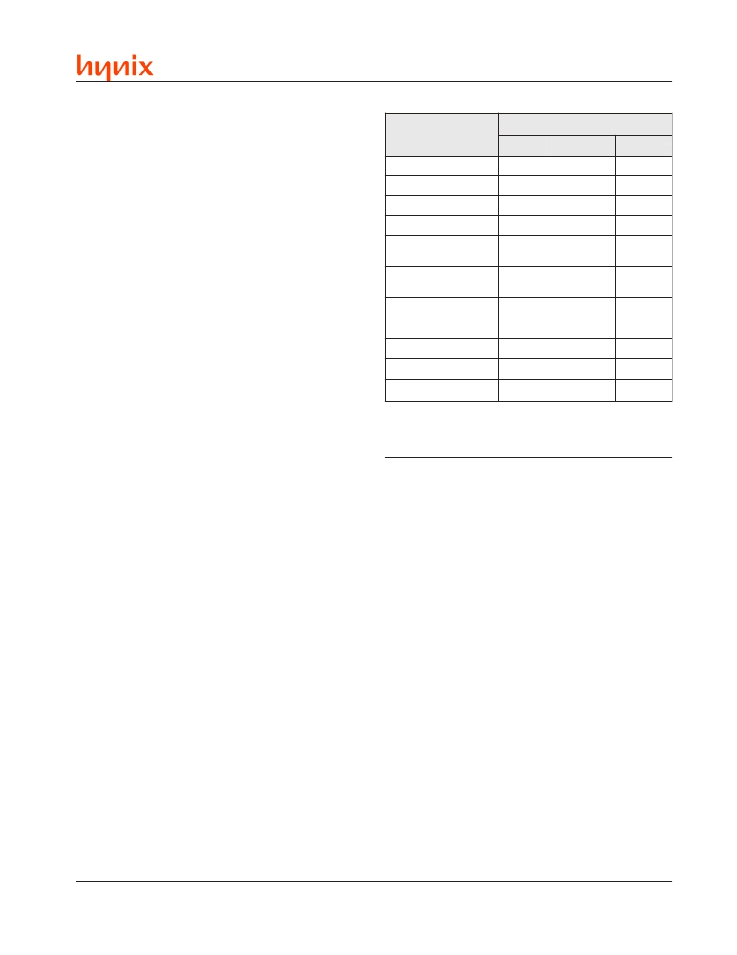
. Table 5
summarizes the composition of the valid command
sequences implemented in the HY29LV400, and
these sequences are fully described in Table 6 and
in the sections that follow.
Writing incorrect address and data values or writ-
ing them in the improper sequence resets the
HY29LV400 to the Read mode.
Reading Data
The device automatically enters the Read mode
after device power-up, after the RESET# input is
asserted and upon the completion of certain com-
mands. Commands are not required to retrieve
data in this mode. See Read Operation section
for additional information.
Reset Command
Writing the Reset command resets the sectors to
the Read or Erase-Suspend mode. Address bits
are don
’
t cares for this command.
As described above, a Reset command is not nor-
mally required to begin reading array data. How-
ever, a Reset command must be issued in order
to read array data in the following cases:
If the device is in the Electronic ID mode, a
Reset command must be written to return to
the Read mode. If the device was in the Erase
Suspend mode when the device entered the
Electronic ID mode, writing the Reset command
returns the device to the Erase Suspend mode.
Note:
When in the Electronic ID bus operation mode,
the device returns to the Read mode when V
is removed
from the A[9] pin. The Reset command is not required
in this case.
If DQ[5] (Exceeded Time Limit) goes High dur-
ing a program or erase operation, a Reset com-
mand must be invoked to return the sectors to
d
e
n
c
a
n
m
e
u
m
q
o
e
C
S
s
e
y
C
s
u
B
f
o
r
e
b
m
u
N
k
c
o
n
U
d
n
a
m
m
o
C
a
D
t
s
a
e
R
d
W
/
B
o
U
o
U
e
R
0
0
2
2
1
0
1
1
0
d
P
y
y
t
s
B
P
a
E
1
e
N
m
a
s
a
s
a
o
p
p
1
0
s
s
B
B
k
k
e
k
c
c
R
c
d
W
p
C
0
1
1
s
s
a
a
o
e
s
p
y
o
U
/
B
m
0
1
1
4
1
1
e
s
a
E
r
e
S
4
1
)
e
N
(
1
d
n
e
p
s
u
S
e
s
a
E
0
1
0
e
m
u
s
e
R
e
s
a
E
0
1
0
D
I
c
o
e
E
2
1
3
e
N
Notes:
1. Any number of Flash array read cycles are permitted.
2. Additional data cycles may follow. See text.
3. Any number of Electronic ID read cycles are permitted.
Table 5. Composition of Command Sequences
the Read mode (or to the Erase Suspend mode
if the device was in Erase Suspend when the
Program command was issued).
The Reset command may also be used to abort
certain command sequences:
In a Sector Erase or Chip Erase command se-
quence, the Reset command may be written
at any time before erasing actually begins, in-
cluding, for the Sector Erase command, be-
tween the cycles that specify the sectors to be
erased (see Sector Erase command descrip-
tion). This aborts the command and resets the
device to the Read mode. Once erasure be-
gins, however, the device ignores the Reset
command until the operation is complete.
In a Program command sequence, the Reset
command may be written between the se-
quence cycles before programming actually be-
gins. This aborts the command and resets the
device to the Read mode, or to the Erase Sus-
pend mode if the Program command sequence
is written while the device is in the Erase Sus-
pend mode. Once programming begins, how-
ever, the device ignores the Reset command
until the operation is complete.
相關(guān)PDF資料 |
PDF描述 |
|---|---|
| HY3-9574A-9 | Analog-to-Digital Converter??? 12-Bit |
| HY3-9574B-9 | Analog-to-Digital Converter??? 12-Bit |
| HY3-9574J-5 | Analog-to-Digital Converter??? 12-Bit |
| HY3-9574K-5 | Analog-to-Digital Converter??? 12-Bit |
| HY-9574 | |
相關(guān)代理商/技術(shù)參數(shù) |
參數(shù)描述 |
|---|---|
| HY29LV400BF55 | 制造商:HYNIX 制造商全稱:Hynix Semiconductor 功能描述:4 Mbit (512K x 8/256K x 16) Low Voltage Flash Memory |
| HY29LV400BF55I | 制造商:HYNIX 制造商全稱:Hynix Semiconductor 功能描述:4 Mbit (512K x 8/256K x 16) Low Voltage Flash Memory |
| HY29LV400BF70 | 制造商:HYNIX 制造商全稱:Hynix Semiconductor 功能描述:4 Mbit (512K x 8/256K x 16) Low Voltage Flash Memory |
| HY29LV400BF70I | 制造商:HYNIX 制造商全稱:Hynix Semiconductor 功能描述:4 Mbit (512K x 8/256K x 16) Low Voltage Flash Memory |
| HY29LV400BF90 | 制造商:HYNIX 制造商全稱:Hynix Semiconductor 功能描述:4 Mbit (512K x 8/256K x 16) Low Voltage Flash Memory |
發(fā)布緊急采購(gòu),3分鐘左右您將得到回復(fù)。