- 您現(xiàn)在的位置:買賣IC網(wǎng) > PDF目錄370471 > HD66732 (Hitachi,Ltd.) Graphics Liquid Crystal Display Controller/Driver Supporting JIS Level-1 and Level-2 Kanji ROM(圖形LCD控制器/驅(qū)動器) PDF資料下載
參數(shù)資料
| 型號: | HD66732 |
| 廠商: | Hitachi,Ltd. |
| 英文描述: | Graphics Liquid Crystal Display Controller/Driver Supporting JIS Level-1 and Level-2 Kanji ROM(圖形LCD控制器/驅(qū)動器) |
| 中文描述: | 圖形液晶顯示控制器/驅(qū)動器支持日標級- 1和第2級漢字光盤(圖形液晶顯示控制器/驅(qū)動器) |
| 文件頁數(shù): | 66/133頁 |
| 文件大小: | 2608K |
| 代理商: | HD66732 |
第1頁第2頁第3頁第4頁第5頁第6頁第7頁第8頁第9頁第10頁第11頁第12頁第13頁第14頁第15頁第16頁第17頁第18頁第19頁第20頁第21頁第22頁第23頁第24頁第25頁第26頁第27頁第28頁第29頁第30頁第31頁第32頁第33頁第34頁第35頁第36頁第37頁第38頁第39頁第40頁第41頁第42頁第43頁第44頁第45頁第46頁第47頁第48頁第49頁第50頁第51頁第52頁第53頁第54頁第55頁第56頁第57頁第58頁第59頁第60頁第61頁第62頁第63頁第64頁第65頁當前第66頁第67頁第68頁第69頁第70頁第71頁第72頁第73頁第74頁第75頁第76頁第77頁第78頁第79頁第80頁第81頁第82頁第83頁第84頁第85頁第86頁第87頁第88頁第89頁第90頁第91頁第92頁第93頁第94頁第95頁第96頁第97頁第98頁第99頁第100頁第101頁第102頁第103頁第104頁第105頁第106頁第107頁第108頁第109頁第110頁第111頁第112頁第113頁第114頁第115頁第116頁第117頁第118頁第119頁第120頁第121頁第122頁第123頁第124頁第125頁第126頁第127頁第128頁第129頁第130頁第131頁第132頁第133頁
HD66732
66
Key Scan Control
The key matrix scanner senses and holds the key states at each rising edge of key strobe signals (KST) that
are output by the HD66732. The key strobe signals are output as time-multiplexed signals from KST0 to
KST3. After passing through the key matrix, these strobe signals are used to sample the key state of eight
inputs KIN0 to KIN7, enabling up to 32 keys to be scanned.
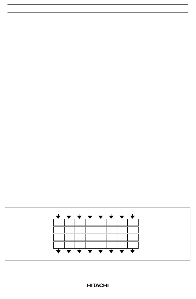
The states of inputs KIN0 to KIN7 are sampled by key strobe signal KST0 and latched into the SCAN0
register. Similarly, the data sampled by strobe signals KST1 to KST3 is latched into the SCAN1 to SCAN3
registers, respectively. Key pressing is stored as 1 in these registers.
The generation cycle and pulse width of the key strobe signals depend on the operating frequency
(oscillation frequency) of the HD66732 and the key scan cycle determined by the KF0 and KF1 bits. For
example, when the operating frequency is 60 kHz and KF0 and KF1 are both 10, the generation cycle is 4.3
ms and the pulse width is 1.1 ms. When the operating frequency (oscillation frequency) is changed, the
above generation cycle and the pulse width are changed in inverse proportion.
In order to compensate for the mechanical features of the keys, such as chattering and noise and for the
key-strobe generation cycle and the pulse width of the HD66732, software should read the scanned data
two to three times in succession to obtain valid data. Multiple keypress combinations should also be
processed in the software.
Up to three keys can be pressed simultaneously. Note, however, that if the third key is pressed on the
intersection between the rows and columns of the first two keys pressed, incorrect data will be sampled. For
three-key input, the third key must be on a separate column or row.
Additionally, the HD66732 supports the key standby mode in which only the key scan circuit enters the
standby state. When 1 is set to the key standby mode setting bit (KSB), only key scanning is stopped. In
this case, as well as in the normal standby mode, the key scan interrupt function can be used. For example,
this function is used when only key scanning is stopped to improve the sensitivity of the wave received by a
radio system during calling.
The input pins KIN0 to KIN7 are pulled up to V
CC
with internal MOS transistors (see the Electrical
Characteristics section). External resistors may also be required to further pull the voltages up when the
internal pull-ups are insufficient for the desired noise margins or for a large key matrix.
SCAN0
SCAN1
SCAN2
SCAN3
D
03
D
02
D
01
D
00
D
13
D
12
D
11
D
10
D
23
D
22
D
21
D
20
D
33
D
32
D
31
D
30
KIN3 KIN2 KIN1 KIN0
(KST0
↑
)
(KST1
↑
)
(KST2
↑
)
(KST3
↑
)
D
04
D
14
D
24
D
34
KIN4
D
05
D
15
D
25
D
35
KIN5
D
06
D
16
D
26
D
36
KIN6
D
07
D
17
D
27
D
37
KIN7
KSD7KSD6 KSD5KSD4 KSD3KSD2 KSD1KSD0
Figure 25 Key Scan Register Configuration
相關(guān)PDF資料 |
PDF描述 |
|---|---|
| HD66740TB0 | 50/MDR/RECP/VERT PRS FIT/M2.6/SCW/30MIN |
| HD66740WTB0 | 112 x 80-dot Graphics LCD Controller/Driver |
| HD66751 | 128 x 128-dot Graphics LCD Controller/Driver with Four-grayscale Functions |
| HD66750TB0 | 122 x 32 pixel format, Compact LCD size |
| HD66750 | 128 x 128-dot Graphics LCD Controller/Driver with Four-grayscale Functions |
相關(guān)代理商/技術(shù)參數(shù) |
參數(shù)描述 |
|---|---|
| HD66735 | 制造商:未知廠家 制造商全稱:未知廠家 功能描述:HD66735 Procedure for setting Standby/Sleep/Display off mode. Technical Update/Device |
| HD66740 | 制造商:未知廠家 制造商全稱:未知廠家 功能描述: |
| HD66740TB0 | 制造商:HITACHI 制造商全稱:Hitachi Semiconductor 功能描述:112 x 80-dot Graphics LCD Controller/Driver |
| HD66740WTB0 | 制造商:HITACHI 制造商全稱:Hitachi Semiconductor 功能描述:112 x 80-dot Graphics LCD Controller/Driver |
| HD66741 | 制造商:HITACHI 制造商全稱:Hitachi Semiconductor 功能描述:128 x 128-dot Graphics LCD Controller/Driver with Four-grayscale Functions |
發(fā)布緊急采購,3分鐘左右您將得到回復。