- 您現(xiàn)在的位置:買賣IC網(wǎng) > PDF目錄362799 > EVAL-AD1953EB (Analog Devices, Inc.) 16-bit fixed point DSP with Flash PDF資料下載
參數(shù)資料
| 型號: | EVAL-AD1953EB |
| 廠商: | Analog Devices, Inc. |
| 元件分類: | 數(shù)字信號處理 |
| 英文描述: | 16-bit fixed point DSP with Flash |
| 中文描述: | 具有閃存的 16 位定點 DSP |
| 文件頁數(shù): | 17/36頁 |
| 文件大?。?/td> | 750K |
| 代理商: | EVAL-AD1953EB |
第1頁第2頁第3頁第4頁第5頁第6頁第7頁第8頁第9頁第10頁第11頁第12頁第13頁第14頁第15頁第16頁當(dāng)前第17頁第18頁第19頁第20頁第21頁第22頁第23頁第24頁第25頁第26頁第27頁第28頁第29頁第30頁第31頁第32頁第33頁第34頁第35頁第36頁
REV. 0
AD1953
–17–
In the look-ahead compressor, the gain has already been reduced
by the time the tone-burst signal arrives at the multiplier input.
Note that when using a look-ahead compressor, it is impor-
tant to set the detector hold time to a value that is at least the
same as the look-ahead delay time, or else the compressor
release will start too soon, resulting in an expanded “tail” of a
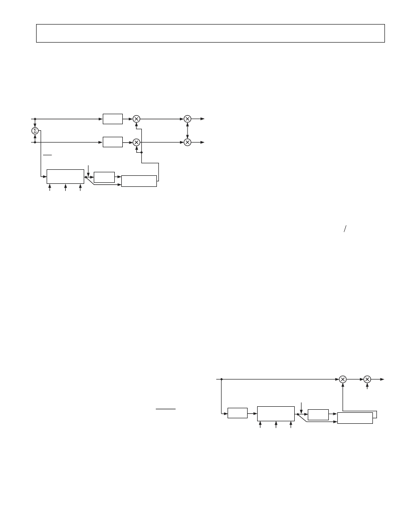
tone burst signal. The complete flow of the left/right dynamics
processor is shown in Figure 13.
LOOK-UP
TABLE
LINEAR
INTERPOLATION
MODIFIED RMS
DETECTOR WITH
LOG OUTPUT
HIGH BITS (1LSB = 3dB)
LOW BITS
TIME
CONSTANT
HOLD
RELEASE
DELAY
DELAY
SPI-PROGRAMMABLE
LOOK-AHEAD DELAY
POST-COMPRESSION
GAIN, SPI-
PROGRAMMABLE
UP TO 30dB
2
(L+R)
Figure 13. Complete Dynamics Flow, Main Channels
The detector path works from a sum of left and right channels
((L+R)/2). This is the normal way that compressors are built,
and it counts on the fact that the main instruments in any stereo
mix are seldom recorded deliberately out of phase, especially in
the lower frequencies, which tend to dominate the energy spectrum
of real music.
The compressor is followed by a block known as post-compression
gain. Most compressors are used to reduce the dynamic range of
music by lowering the gain during loud signal passages. This
results in an overall loss of volume. This loss can be made up by
introducing gain after the compressor. In the AD1953, the
coefficient format used is 2.20, which has a maximum floating-
point representation of slightly less than 2.0. This means the
maximum gain that can be achieved in a single instruction is 6 dB.
To get more gain, the program in the AD1953 uses a cascade
of five multipliers to achieve up to 30 dB of post-compression gain.
To program the compressor/limiter, the following formulas may
be used to determine the 22-bit numbers (in 2.20 format) to be
entered into the parameter RAM.
RMS Time Constant
This can be best expressed by entering the time constant in
terms of dB/sec “raw” release rate (without the peak-riding circuit).
The attack rate is a rather complicated formula that depends on
the change in amplitude of the input sine wave.
rms tconst
_
parameter
release rate
.
10 0
f
S
_
. –
1 0 10
=
×
where
rms_tconst_parameter
= fractional number to enter into
the
SPI RAM (after converting to 22-bit 2.20 format)
release_rate
= release rate of the raw rms detector in dB/sec. This
must be negative.
f
S
= audio sampling rate.
RMS Hold Time
rms holdtime
where
rms_holdtime_parameter
= integer number to enter into the SPI RAM
parameter
f
hold time
_
S
_
_
int
=
×
(
)
f
S
= audio sample rate
Hold_time
= absolute time to wait before starting the release
ramp-down of the detector output
int() = integer part of expression
RMS Release Rate
rms decay
Where
rms_decay_parameter
= decimal integer number to enter
into the SPI RAM
rms_decay
= decay rate in dB/sec
int() = integer part of expression
Look-Ahead Delay
parameter
rms decay
_
(
_
_
int
/1 096
=
)
Lookahead delay
Where
Lookahead_delay
= predictive compressor delay in abso-
lute time
f
S
= audio sample rate
The maximum
Lookahead_delay_parameter
value is 100.
Post-Compression Gain
Post
compression
Post
compression
_
_
parameter
Lookahead delay
f
S
_
_
_
=
×
gain
gain linear
_
parameter
_
_
_
=
)
(
∧
1 5
Where
Post_compression gain_linear
is the linear post-compression
gain
^ = raise to the power
Subwoofer Compressor/Limiter
The subwoofer compressor/limiter differs from the left/right
compressor in the following ways:
1.The subwoofer compressor operates on a weighted sum of left
and right inputs (aa
×
Left + bb
×
Right), where aa and bb are
both programmable.
2.The detector input has a biquad filter in series with the input
in order to implement frequency-dependent compression
thresholds.
3.There is no predictive compression, as presumably the input
signals are filtered to pass only low frequencies, and therefore
transient overshoots are not a problem.
The subwoofer compressor signal flow is shown in Figure 14.
LOOK-UP
TABLE
LINEAR
INTERPOLATION
MODIFIED RMS
DETECTOR WITH
LOG OUTPUT
HIGH BITS (1LSB = 3dB)
LOW BITS
TIME
CONSTANT
HOLD
RELEASE
V
IN
_SUB = K1 LEFT_IN + K2 RIGHT_IN
POST-COMPRESSION
GAIN, SPI-
PROGRAMMABLE
UP TO 30dB
BIQUAD
FILTER
Figure 14. Signal Flow for Subwoofer Compressor
The biquad filter before the detector can be used to implement
a frequency-dependent compression threshold. For example,
assume that the overload point of the woofer is strongly fre-
quency-dependent. In this case, one would have to set the
compressor threshold to a value that corresponded to the most
sensitive overload frequency of the woofer. If the input signal
happened to be mostly in a frequency range where the woofer
相關(guān)PDF資料 |
PDF描述 |
|---|---|
| EVAL-AD1958EB | PLL/Multibit DAC |
| EVAL-AD1959EB | PLL/Multibit DAC |
| EVAL-AD1974EB | 4 ADC with PLL, 192 kHz, 24-Bit Codec |
| EVAl-AD1974EBZ | 4 ADC with PLL, 192 kHz, 24-Bit Codec |
| EVAL-AD1990EB | Audio Switching Amplifier |
相關(guān)代理商/技術(shù)參數(shù) |
參數(shù)描述 |
|---|---|
| EVAL-AD1953EBZ | 制造商:Analog Devices 功能描述:EVAL BRD FOR 3 CH 24 BIT SIG-PROCESS DAC - Bulk |
| EVAL-AD1954EB | 制造商:Rochester Electronics LLC 功能描述:EVAL BRD FOR 3 CH 24 BIT SIG-PROCESS DAC - Bulk 制造商:Analog Devices 功能描述: |
| EVAL-AD1955EB | 制造商:Analog Devices 功能描述:Evaluation Board For AD1955 制造商:Analog Devices 功能描述:EVAL BOARD FOR 24 BIT 192KHZ DAC 120 DB - Bulk 制造商:Rochester Electronics LLC 功能描述:EVAL BOARD FOR 24 BIT 192KHZ DAC 120 DB - Bulk |
| EVAL-AD1955EBZ | 功能描述:BOARD EVAL FOR AD1955 RoHS:是 類別:編程器,開發(fā)系統(tǒng) >> 評估板 - 數(shù)模轉(zhuǎn)換器 (DAC) 系列:- 產(chǎn)品培訓(xùn)模塊:Lead (SnPb) Finish for COTS Obsolescence Mitigation Program 標(biāo)準(zhǔn)包裝:1 系列:- DAC 的數(shù)量:4 位數(shù):12 采樣率(每秒):- 數(shù)據(jù)接口:串行,SPI? 設(shè)置時間:3µs DAC 型:電流/電壓 工作溫度:-40°C ~ 85°C 已供物品:板 已用 IC / 零件:MAX5581 |
| EVAL-AD1955EBZ | 制造商:Analog Devices 功能描述:EVAL BOARD, AD1955 STEREO DIGITAL AUDIO |
發(fā)布緊急采購,3分鐘左右您將得到回復(fù)。