- 您現(xiàn)在的位置:買(mǎi)賣(mài)IC網(wǎng) > PDF目錄97926 > EPF10K100BFC256-2DX ASIC PDF資料下載
參數(shù)資料
| 型號(hào): | EPF10K100BFC256-2DX |
| 英文描述: | ASIC |
| 中文描述: | 專用集成電路 |
| 文件頁(yè)數(shù): | 72/120頁(yè) |
| 文件大小: | 1901K |
| 代理商: | EPF10K100BFC256-2DX |
第1頁(yè)第2頁(yè)第3頁(yè)第4頁(yè)第5頁(yè)第6頁(yè)第7頁(yè)第8頁(yè)第9頁(yè)第10頁(yè)第11頁(yè)第12頁(yè)第13頁(yè)第14頁(yè)第15頁(yè)第16頁(yè)第17頁(yè)第18頁(yè)第19頁(yè)第20頁(yè)第21頁(yè)第22頁(yè)第23頁(yè)第24頁(yè)第25頁(yè)第26頁(yè)第27頁(yè)第28頁(yè)第29頁(yè)第30頁(yè)第31頁(yè)第32頁(yè)第33頁(yè)第34頁(yè)第35頁(yè)第36頁(yè)第37頁(yè)第38頁(yè)第39頁(yè)第40頁(yè)第41頁(yè)第42頁(yè)第43頁(yè)第44頁(yè)第45頁(yè)第46頁(yè)第47頁(yè)第48頁(yè)第49頁(yè)第50頁(yè)第51頁(yè)第52頁(yè)第53頁(yè)第54頁(yè)第55頁(yè)第56頁(yè)第57頁(yè)第58頁(yè)第59頁(yè)第60頁(yè)第61頁(yè)第62頁(yè)第63頁(yè)第64頁(yè)第65頁(yè)第66頁(yè)第67頁(yè)第68頁(yè)第69頁(yè)第70頁(yè)第71頁(yè)當(dāng)前第72頁(yè)第73頁(yè)第74頁(yè)第75頁(yè)第76頁(yè)第77頁(yè)第78頁(yè)第79頁(yè)第80頁(yè)第81頁(yè)第82頁(yè)第83頁(yè)第84頁(yè)第85頁(yè)第86頁(yè)第87頁(yè)第88頁(yè)第89頁(yè)第90頁(yè)第91頁(yè)第92頁(yè)第93頁(yè)第94頁(yè)第95頁(yè)第96頁(yè)第97頁(yè)第98頁(yè)第99頁(yè)第100頁(yè)第101頁(yè)第102頁(yè)第103頁(yè)第104頁(yè)第105頁(yè)第106頁(yè)第107頁(yè)第108頁(yè)第109頁(yè)第110頁(yè)第111頁(yè)第112頁(yè)第113頁(yè)第114頁(yè)第115頁(yè)第116頁(yè)第117頁(yè)第118頁(yè)第119頁(yè)第120頁(yè)
Altera Corporation
55
FLEX 10KE Embedded Programmable Logic Family Data Sheet
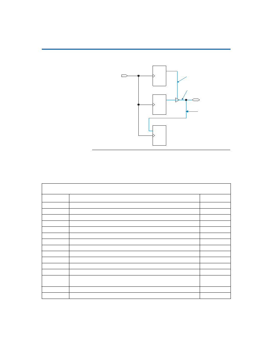
Figure 28. Synchronous Bidirectional Pin External Timing Model
parameters and their symbols. Detailed timing information for these
devices will be released as it is available.
PRN
CLRN
DQ
PRN
CLRN
DQ
PRN
CLRN
DQ
Dedicated
Clock
Bidirectional
Pin
Output Register
tINSUBIDIR
tOUTCOBIDIR
tXZBIDIR
tZXBIDIR
tINHBIDIR
OE Register
Input Register
Table 24. LE Timing Microparameters (Part 1 of 2)
Symbol
Parameter
Condition
tLUT
LUT delay for data-in
tCLUT
LUT delay for carry-in
tRLUT
LUT delay for LE register feedback
tPACKED
Data-in to packed register delay
tEN
LE register enable delay
tCICO
Carry-in to carry-out delay
tCGEN
Data-in to carry-out delay
tCGENR
LE register feedback to carry-out delay
tCASC
Cascade-in to cascade-out delay
tC
LE register control signal delay
tCO
LE register clock-to-output delay
tCOMB
Combinatorial delay
tSU
LE register setup time for data and enable signals before clock; LE register
recovery time after asynchronous clear, preset, or load
tH
LE register hold time for data and enable signals after clock
tPRE
LE register preset delay
相關(guān)PDF資料 |
PDF描述 |
|---|---|
| EPF10K100BFC256-3DX | ASIC |
| EPF10K100BFI256-1DX | ASIC |
| EPF10K100BFI256-2DX | ASIC |
| EPF10K100BFI256-3DX | ASIC |
| EPF10K100BQC208-1DX | ASIC |
相關(guān)代理商/技術(shù)參數(shù) |
參數(shù)描述 |
|---|---|
| EPF10K100BFC256-3DX | 制造商:未知廠家 制造商全稱:未知廠家 功能描述:ASIC |
| EPF10K100BFI256-1DX | 制造商:未知廠家 制造商全稱:未知廠家 功能描述:ASIC |
| EPF10K100BFI256-2DX | 制造商:未知廠家 制造商全稱:未知廠家 功能描述:ASIC |
| EPF10K100BFI256-3DX | 制造商:未知廠家 制造商全稱:未知廠家 功能描述:ASIC |
| EPF10K100BQC208-1 | 制造商:Rochester Electronics LLC 功能描述:- Bulk |
發(fā)布緊急采購(gòu),3分鐘左右您將得到回復(fù)。