- 您現(xiàn)在的位置:買賣IC網(wǎng) > PDF目錄352474 > AM29BDS640GTD4WSI (SPANSION LLC) 64 Megabit (4 M x 16-Bit) CMOS 1.8 Volt-only Simultaneous Read/Write, Burst Mode Flash Memory PDF資料下載
參數(shù)資料
| 型號: | AM29BDS640GTD4WSI |
| 廠商: | SPANSION LLC |
| 元件分類: | DRAM |
| 英文描述: | 64 Megabit (4 M x 16-Bit) CMOS 1.8 Volt-only Simultaneous Read/Write, Burst Mode Flash Memory |
| 中文描述: | 4M X 16 FLASH 1.8V PROM, 14 ns, PBGA80 |
| 封裝: | 11 X 12 MM, 0.80 MM PITCH, FBGA-80 |
| 文件頁數(shù): | 17/65頁 |
| 文件大?。?/td> | 899K |
| 代理商: | AM29BDS640GTD4WSI |
第1頁第2頁第3頁第4頁第5頁第6頁第7頁第8頁第9頁第10頁第11頁第12頁第13頁第14頁第15頁第16頁當(dāng)前第17頁第18頁第19頁第20頁第21頁第22頁第23頁第24頁第25頁第26頁第27頁第28頁第29頁第30頁第31頁第32頁第33頁第34頁第35頁第36頁第37頁第38頁第39頁第40頁第41頁第42頁第43頁第44頁第45頁第46頁第47頁第48頁第49頁第50頁第51頁第52頁第53頁第54頁第55頁第56頁第57頁第58頁第59頁第60頁第61頁第62頁第63頁第64頁第65頁
October 31, 2002
Am29BDS640G
23
AD V A NCE
INF O R M A T IO N
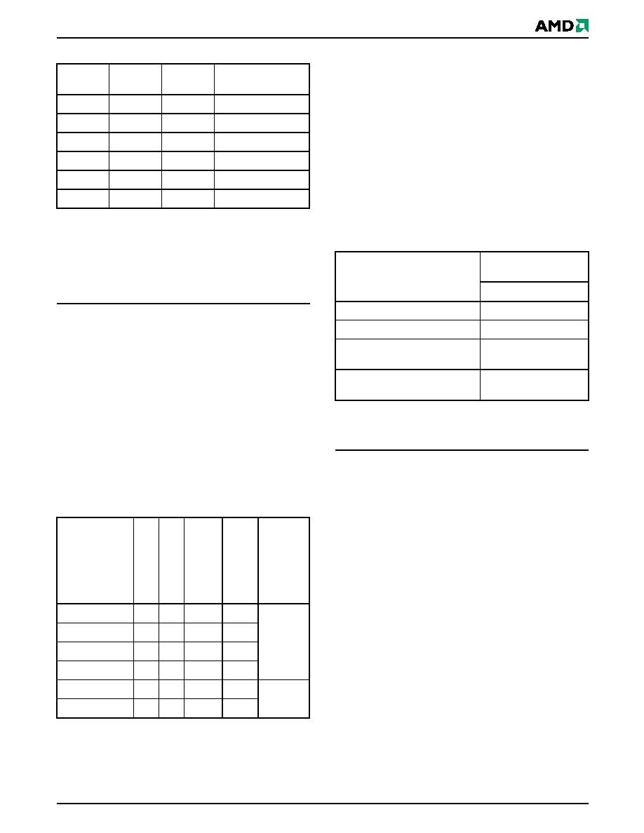
Table 8.
Programmable Wait State Settings
Notes:
1. Upon power-up or hardware reset, the default setting is
seven wait states.
2. RDY will default to being active with data when the Wait
State Setting is set to a total initial access cycle of 2.
3. Assumes even address.
It is recommended that the wait state command
sequence be written, even if the default wait state value
is desired, to ensure the device is set as expected. A
hardware reset will set the wait state to the default set-
ting.
Reduced Wait-State Handshaking Option
If the device is equipped with the reduced wait-state
handshaking option, the host system should set
address bits A14–A12 to 010 for a clock frequency of
40 MHz or to 011 for a clock frequency of 54 MHz for
the system/device to execute at maximum speed.
Table 9 describes the typical number of clock cycles
(wait states) for various conditions.
Table 9.
Initial Access Cycles vs. Frequency
Note: In the 8-, 16- and 32-word burst read modes, the
address pointer does not cross 64-word boundaries
(addresses which are multiples of 3Fh).
The autoselect function allows the host system to
determine whether the flash device is enabled for
reduced wait-state handshaking. See the “Autoselect
Command Sequence” section for more information.
Standard Handshaking Operation
For optimal burst mode performance on devices
without the reduced wait-state handshaking option, the
host system must set the appropriate number of wait
states in the flash device depending on the clock fre-
quency.
Table 10 describes the typical number of clock cycles
(wait states) for various conditions with A14–A12 set to
101.
Table 10.
Wait States for Standard Handshaking
* In the 8-, 16- and 32-word burst read modes, the address
pointer does not cross 64-word boundaries (addresses
which are multiples of 3Fh).
Burst Read Mode Configuration
The device supports four different burst read modes:
continuous mode, and 8, 16, and 32 word linear wrap
around modes. A continuous sequence begins at the
starting address and advances the address pointer
until the burst operation is complete. If the highest
address in the device is reached during the continuous
burst read mode, the address pointer wraps around to
the lowest address.
For example, an eight-word linear burst with wrap
around begins on the starting burst address written to
the device and then proceeds until the next 8 word
boundary. The address pointer then returns to the first
word of the burst sequence, wrapping back to the
starting location. The sixteen- and thirty-two linear
wrap around modes operate in a fashion similar to the
eight-word mode.
Table 11 shows the address bits and settings for the
four burst read modes.
A14
A13
A12
Total Initial Access
Cycles
00
0
2
00
1
3
01
0
4
01
1
5
10
0
6
10
1
7
System
Frequency
Range
Eve
n
In
itial
Addr
.
O
dd
I
n
itia
lAddr
.
Eve
n
In
itial
Addr
.
w
ith
Bo
unda
ry
O
dd
I
n
itia
lAddr
.
w
ith
Bo
unda
ry
Device
Speed
Rating
6–11 MHz
2
3
4
40 MHz
12–23 MHz
2
3
4
5
24–33 MHz
3
4
5
6
34–40 MHz
4
5
6
7
40–47 MHz
4
5
6
7
54 MHz
48–54 MHz
5
6
7
8
Conditions at Address
Typical No. of Clock
Cycles after AVD# Low
40/54 MHz
Initial address is even
7
Initial address is odd
7
Initial address is even,
and is at boundary crossing*
7
Initial address is odd,
and is at boundary crossing*
7
相關(guān)PDF資料 |
PDF描述 |
|---|---|
| AM29PDL127H88PCI | 128 Megabit (8 M x 16-Bit) CMOS 3.0 Volt-only, Page Mode Simultaneous Read/Write Flash Memory with Enhanced VersatileIO Control |
| AM29PDL127H88VKIN | 128 Megabit (8 M x 16-Bit) CMOS 3.0 Volt-only, Page Mode Simultaneous Read/Write Flash Memory with Enhanced VersatileIO Control |
| AM29PDL127H | 128 Megabit (8 M x 16-Bit) CMOS 3.0 Volt-only, Page Mode Simultaneous Read/Write Flash Memory with Enhanced VersatileIO Control |
| AM29PDL127H20PCI | 128 Megabit (8 M x 16-Bit) CMOS 3.0 Volt-only, Page Mode Simultaneous Read/Write Flash Memory with Enhanced VersatileIO Control |
| AM29PDL127H20PCIN | 128 Megabit (8 M x 16-Bit) CMOS 3.0 Volt-only, Page Mode Simultaneous Read/Write Flash Memory with Enhanced VersatileIO Control |
相關(guān)代理商/技術(shù)參數(shù) |
參數(shù)描述 |
|---|---|
| AM29BDS643GT5KVAI | 制造商:Spansion 功能描述:FLASH PARALLEL 1.8V 64MBIT 4MX16 55NS 44FBGA - Trays |
| AM29BL802CB-65RZET | 制造商:Spansion 功能描述: |
| AM29C01WW WAF | 制造商:Advanced Micro Devices 功能描述: |
| AM29C10API | 制造商:Rochester Electronics LLC 功能描述:- Bulk |
| AM29C10AWW DIE | 制造商:Advanced Micro Devices 功能描述: |
發(fā)布緊急采購,3分鐘左右您將得到回復(fù)。