- 您現(xiàn)在的位置:買(mǎi)賣(mài)IC網(wǎng) > PDF目錄68811 > 71M6542F-IGTR/F (MAXIM INTEGRATED PRODUCTS INC) SPECIALTY ANALOG CIRCUIT, PQFP100 PDF資料下載
參數(shù)資料
| 型號(hào): | 71M6542F-IGTR/F |
| 廠商: | MAXIM INTEGRATED PRODUCTS INC |
| 元件分類(lèi): | 模擬信號(hào)調(diào)理 |
| 英文描述: | SPECIALTY ANALOG CIRCUIT, PQFP100 |
| 封裝: | LEAD FREE, LQFP-100 |
| 文件頁(yè)數(shù): | 105/165頁(yè) |
| 文件大小: | 2208K |
| 代理商: | 71M6542F-IGTR/F |
第1頁(yè)第2頁(yè)第3頁(yè)第4頁(yè)第5頁(yè)第6頁(yè)第7頁(yè)第8頁(yè)第9頁(yè)第10頁(yè)第11頁(yè)第12頁(yè)第13頁(yè)第14頁(yè)第15頁(yè)第16頁(yè)第17頁(yè)第18頁(yè)第19頁(yè)第20頁(yè)第21頁(yè)第22頁(yè)第23頁(yè)第24頁(yè)第25頁(yè)第26頁(yè)第27頁(yè)第28頁(yè)第29頁(yè)第30頁(yè)第31頁(yè)第32頁(yè)第33頁(yè)第34頁(yè)第35頁(yè)第36頁(yè)第37頁(yè)第38頁(yè)第39頁(yè)第40頁(yè)第41頁(yè)第42頁(yè)第43頁(yè)第44頁(yè)第45頁(yè)第46頁(yè)第47頁(yè)第48頁(yè)第49頁(yè)第50頁(yè)第51頁(yè)第52頁(yè)第53頁(yè)第54頁(yè)第55頁(yè)第56頁(yè)第57頁(yè)第58頁(yè)第59頁(yè)第60頁(yè)第61頁(yè)第62頁(yè)第63頁(yè)第64頁(yè)第65頁(yè)第66頁(yè)第67頁(yè)第68頁(yè)第69頁(yè)第70頁(yè)第71頁(yè)第72頁(yè)第73頁(yè)第74頁(yè)第75頁(yè)第76頁(yè)第77頁(yè)第78頁(yè)第79頁(yè)第80頁(yè)第81頁(yè)第82頁(yè)第83頁(yè)第84頁(yè)第85頁(yè)第86頁(yè)第87頁(yè)第88頁(yè)第89頁(yè)第90頁(yè)第91頁(yè)第92頁(yè)第93頁(yè)第94頁(yè)第95頁(yè)第96頁(yè)第97頁(yè)第98頁(yè)第99頁(yè)第100頁(yè)第101頁(yè)第102頁(yè)第103頁(yè)第104頁(yè)當(dāng)前第105頁(yè)第106頁(yè)第107頁(yè)第108頁(yè)第109頁(yè)第110頁(yè)第111頁(yè)第112頁(yè)第113頁(yè)第114頁(yè)第115頁(yè)第116頁(yè)第117頁(yè)第118頁(yè)第119頁(yè)第120頁(yè)第121頁(yè)第122頁(yè)第123頁(yè)第124頁(yè)第125頁(yè)第126頁(yè)第127頁(yè)第128頁(yè)第129頁(yè)第130頁(yè)第131頁(yè)第132頁(yè)第133頁(yè)第134頁(yè)第135頁(yè)第136頁(yè)第137頁(yè)第138頁(yè)第139頁(yè)第140頁(yè)第141頁(yè)第142頁(yè)第143頁(yè)第144頁(yè)第145頁(yè)第146頁(yè)第147頁(yè)第148頁(yè)第149頁(yè)第150頁(yè)第151頁(yè)第152頁(yè)第153頁(yè)第154頁(yè)第155頁(yè)第156頁(yè)第157頁(yè)第158頁(yè)第159頁(yè)第160頁(yè)第161頁(yè)第162頁(yè)第163頁(yè)第164頁(yè)第165頁(yè)
44
2008–2011 Teridian Semiconductor Corporation
v1.1
External MPU Interrupts
The seven external interrupts are the interrupts external to the 80515 core, i.e., signals that originate in
other parts of the 71M654x, for example the CE, DIO, RTC, or EEPROM interface.
The external interrupts are connected as shown in Table 32. The polarity of interrupts 2 and 3 is
programmable in the MPU via the I3FR and I2FR bits in T2CON (SFR 0xC8). Interrupts 2 and 3 should be
programmed for falling sensitivity (I3FR = I2FR = 0). The generic 8051 MPU literature states that interrupts 4
through 6 are defined as rising-edge sensitive. Thus, the hardware signals attached to interrupts 5
and 6 are inverted to achieve the edge polarity shown in Table 32.
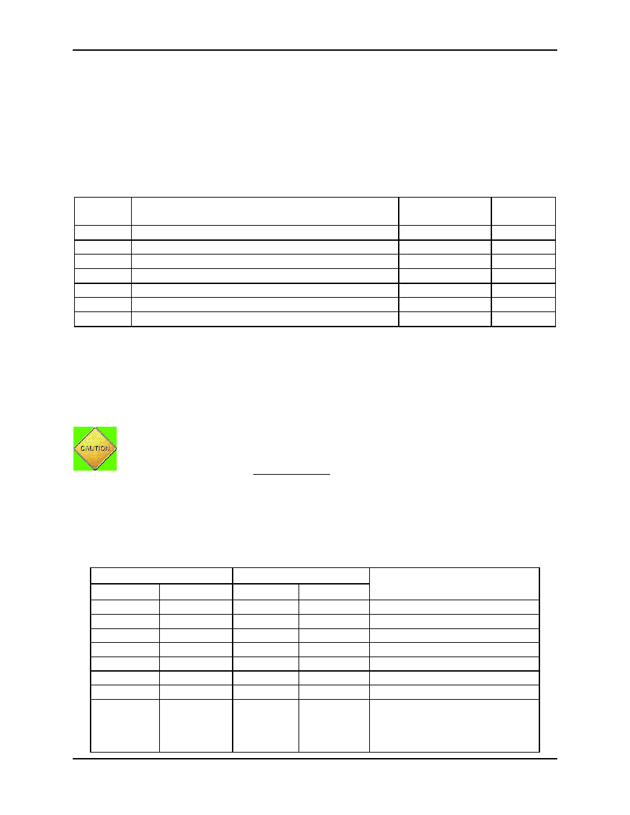
Table 32: External MPU Interrupts
External
Interrupt
Connection
Polarity
Flag Reset
0
Digital I/O
see 2.5.8
automatic
1
Digital I/O
see 2.5.8
automatic
2
CE_PULSE
rising
automatic
3
CE_BUSY
falling
automatic
4
VSTAT (VSTAT[2:0] changed)
rising
automatic
5
EEPROM busy (falling), SPI (rising)
automatic
6
XFER_BUSY (falling), RTC_1SEC, RTC_1MIN, RTC_T
falling
manual
External interrupt 0 and 1 can be mapped to pins on the device using DIO resource maps. See 2.5.8
Digital I/O for more information.
SFR enable bits must be set to permit any of these interrupts to occur. Likewise, each interrupt has its own
flag bit, which is set by the interrupt hardware, and reset by the MPU interrupt handler. XFER_BUSY,
RTC_1SEC, RTC_1MIN, RTC_T, SPI, PLLRISE and PLLFALL have their own enable and flag bits in
addition to the interrupt 6, 4 and enable and flag bits (see Table 33: Interrupt Enable and Flag Bits).
IE0 through IEX6 are cleared automatically when the hardware vectors to the interrupt handler.
The other flags, IE_XFER through IE_VPULSE, are cleared by writing a zero to them.
Since these bits are in an SFR bit addressable byte, common practice would be to clear them
with a bit operation, but this must be avoided. The hardware implements bit operations as a
byte wide read-modify-write hardware macro. If an interrupt occurs after the read, but before
the write, its flag cleared unintentionally.
The proper way to clear the flag bits is to write a byte mask consisting of all ones except for a
zero in the location of the bit to be cleared. The flag bits are configured in hardware to ignore
ones written to them.
Table 33: Interrupt Enable and Flag Bits
Interrupt Enable
Interrupt Flag
Interrupt Description
Name
Location
Name
Location
EX0
SFR 0xA8[[0]
IE0
SFR 0x88[1]
External interrupt 0
EX1
SFR 0xA8[2]
IE1
SFR 0x88[3]
External interrupt 1
EX2
SFR 0xB8[1]
IEX2
SFR 0xC0[1]
External interrupt 2
EX3
SFR 0xB8[2]
IEX3
SFR 0xC0[2]
External interrupt 3
EX4
SFR 0xB8[3]
IEX4
SFR 0xC0[3]
External interrupt 4
EX5
SFR 0xB8[4]
IEX5
SFR 0xC0[4]
External interrupt 5
EX6
SFR 0xB8[5]
IEX6
SFR 0xC0[5]
External interrupt 6
EX_XFER
EX_RTC1S
EX_RTC1M
EX_RTCT
0x2700[0]
0x2700[1]
0x2700[2]
0x2700[4]
IE_XFER
IE_RTC1S
IE_RTC1M
IE_RTCT
SFR 0xE8[0]
SFR 0xE8[1]
SFR E0x8[2]
SFR 0xE8[4]
XFER_BUSY interrupt (int 6)
RTC_1SEC interrupt (int 6)
RTC_1MIN interrupt (int 6)
RTC_T alarm clock interrupt (int 6)
相關(guān)PDF資料 |
PDF描述 |
|---|---|
| 71M6541D-IGT/F | SPECIALTY ANALOG CIRCUIT, PQFP64 |
| 71M6542G-IGT/F | SPECIALTY ANALOG CIRCUIT, PQFP100 |
| 71M6541G-IGT/F | SPECIALTY ANALOG CIRCUIT, PQFP64 |
| 71M6541F-IGT/F | SPECIALTY ANALOG CIRCUIT, PQFP64 |
| 71M6543F-IGT/F | SPECIALTY ANALOG CIRCUIT, PQFP100 |
相關(guān)代理商/技術(shù)參數(shù) |
參數(shù)描述 |
|---|---|
| 71M6542FT-IGT/F | 制造商:Maxim Integrated Products 功能描述:1-PHASE SOC 128KB WITH PREC TEMP SENSOR - Rail/Tube |
| 71M6542FT-IGTR/F | 制造商:Maxim Integrated Products 功能描述:1-PHASE SOC, 64KB FLASH, PRES TEMP SENSOR - Tape and Reel |
| 71M6542G | 制造商:未知廠家 制造商全稱(chēng):未知廠家 功能描述:71M6541D/71M6541F/71M6541G/71M6542F/71M6542G 是 TeridianTM 的第4 代高集成度單相電表SoC |
| 71M6542G-IGT/F | 功能描述:計(jì)量片上系統(tǒng) - SoC 1-Phase Metering SOC with 128KB Flash RoHS:否 制造商:Maxim Integrated 核心:80515 MPU 處理器系列:71M6511 類(lèi)型:Metering SoC 最大時(shí)鐘頻率:70 Hz 程序存儲(chǔ)器大小:64 KB 數(shù)據(jù) RAM 大小:7 KB 接口類(lèi)型:UART 可編程輸入/輸出端數(shù)量:12 片上 ADC: 安裝風(fēng)格:SMD/SMT 封裝 / 箱體:LQFP-64 封裝:Reel |
| 71M6542G-IGTR/F | 制造商:Maxim Integrated Products 功能描述:- Tape and Reel |
發(fā)布緊急采購(gòu),3分鐘左右您將得到回復(fù)。