- 您現(xiàn)在的位置:買賣IC網(wǎng) > PDF目錄358635 > 38C1 (Mitsubishi Electric Corporation) DIODE ZENER SINGLE 200mW 24Vz 0.05mA-Izt 0.05 0.05uA-Ir 18.2 SOD-323 3K/REEL PDF資料下載
參數(shù)資料
| 型號: | 38C1 |
| 廠商: | Mitsubishi Electric Corporation |
| 英文描述: | DIODE ZENER SINGLE 200mW 24Vz 0.05mA-Izt 0.05 0.05uA-Ir 18.2 SOD-323 3K/REEL |
| 中文描述: | 單芯片8位CMOS微機(jī) |
| 文件頁數(shù): | 53/59頁 |
| 文件大小: | 1063K |
| 代理商: | 38C1 |
第1頁第2頁第3頁第4頁第5頁第6頁第7頁第8頁第9頁第10頁第11頁第12頁第13頁第14頁第15頁第16頁第17頁第18頁第19頁第20頁第21頁第22頁第23頁第24頁第25頁第26頁第27頁第28頁第29頁第30頁第31頁第32頁第33頁第34頁第35頁第36頁第37頁第38頁第39頁第40頁第41頁第42頁第43頁第44頁第45頁第46頁第47頁第48頁第49頁第50頁第51頁第52頁當(dāng)前第53頁第54頁第55頁第56頁第57頁第58頁第59頁

53
38C1 Group
SINGLE-CHIP 8-BIT CMOS MICROCOMPUTER
MITSUBISHI MICROCOMPUTERS
PRELIMINARY
Notice: This is not a final specification.
Some parametric limits are subject to change.
Reset input “L” pulse width
Main clock input cycle time (X
IN
input)
Main clock input “H” pulse width
Main clock input “L” pulse width
CNTR
0
, CNTR
1
input cycle time
CNTR
0
, CNTR
1
input “H” pulse width
CNTR
0
, CNTR
1
input “L” pulse width
INT
0
, INT
1
input “H” pulse width
INT
0
, INT
1
input “L” pulse width
Serial I/O clock input cycle time
Serial I/O clock input “H” pulse width
Serial I/O clock input “L” pulse width
Serial I/O input setup time
Serial I/O input hold time
t
w
(RESET)
t
c
(X
IN
)
t
wH
(X
IN
)
t
wL
(X
IN
)
t
c
(CNTR)
t
wH
(CNTR)
t
wL
(CNTR)
t
wH
(INT)
t
wL
(INT)
t
c
(S
CLK
)
t
wH
(S
CLK
)
t
wL
(S
CLK
)
t
su
(S
IN
-S
CLK
)
t
h
(S
CLK
-S
IN
)
Limits
Typ.
μ
s
ns
ns
ns
ns
ns
ns
ns
ns
ns
ns
ns
ns
ns
Parameter
Min.
2
125
50
50
250
105
105
80
80
1000
400
400
200
200
Max.
Symbol
Unit
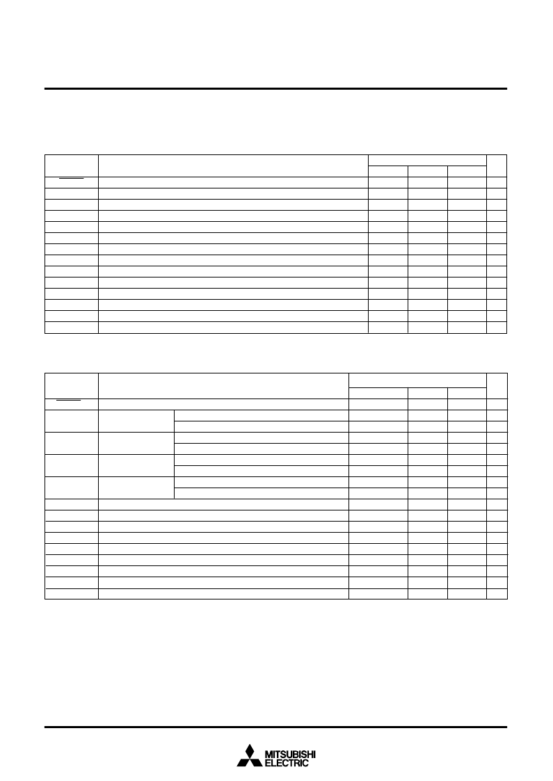
Table 20 Timing requirements 2
(Vcc =1.8 to 4.0 V (2.2 to 4.0 V for One Time PROM version), Vss = 0 V, Ta = –20 to 85
°
C, unless otherwise noted)
Timing Requirements And Switching Characteristics
Table 19 Timing requirements 1
(Vcc = 4.0 to 5.5 V, Vss = 0 V, Ta = –20 to 85
°
C, unless otherwise noted)
t
w
(RESET)
t
c
(X
IN
)
t
wH
(X
IN
)
t
wL
(X
IN
)
t
c
(CNTR)
t
wH
(CNTR)
t
wL
(CNTR)
t
wH
(INT)
t
wL
(INT)
t
c
(S
CLK
)
t
wH
(S
CLK
)
t
wL
(S
CLK
)
t
su
(RxD-S
CLK
)
t
h
(S
CLK
-RxD)
Limits
μ
s
ns
ns
ns
ns
ns
ns
ns
ns
ns
ns
ns
ns
ns
ns
ns
ns
ns
Parameter
Min.
2
125
166
50
70
50
70
1000/V
CC
1000/(5
V
CC
–8)
tc(CNTR)/2–20
tc(CNTR)/2–20
230
230
2000
950
950
400
200
Typ.
Max.
Symbol
Unit
Reset input “L” pulse width
Main clock input
cycle time (X
IN
input)
Main clock input
“H” pulse width
Main clock input
“L” pulse width
CNTR
0
, CNTR
1
input
cycle time
CNTR
0
, CNTR
1
input “H” pulse width
CNTR
0
, CNTR
1
input “L” pulse width
INT
0
, INT
1
input “H” pulse width
INT
0
, INT
1
input “L” pulse width
Serial I/O clock input cycle time
Serial I/O clock input “H” pulse width
Serial I/O clock input “L” pulse width
Serial I/O input setup time
Serial I/O input hold time
2.0 V (One Time PROM version: 2.5 V)
≤
V
CC
≤
4.0 V
V
CC
≤
2.0 V (One Time PROM version: 2.5 V)
2.0 V (One Time PROM version: 2.5 V)
≤
V
CC
≤
4.0 V
V
CC
≤
2.0 V (One Time PROM version: 2.5 V)
2.0 V (One Time PROM version: 2.5 V)
≤
V
CC
≤
4.0 V
V
CC
≤
2.0 V (One Time PROM version: 2.5 V)
2.0 V (One Time PROM version: 2.5 V)
≤
V
CC
≤
4.0 V
V
CC
≤
2.0 V (One Time PROM version: 2.5 V)
相關(guān)PDF資料 |
PDF描述 |
|---|---|
| 38C2 | SINGLE-CHIP 8-BIT CMOS MICROCOMPUTER |
| 38D5 | SINGLE-CHIP 8-BIT CMOS MICROCOMPUTER |
| 38F1222 | 300mA LDO Linear Regulators with Internal Microprocessor Reset Circuit |
| TA5M | STECKER DIN MINI 5POL |
| 70B5031 | KUPPLUNG DIN MINI 5POL |
相關(guān)代理商/技術(shù)參數(shù) |
參數(shù)描述 |
|---|---|
| 38C2 | 制造商:MITSUBISHI 制造商全稱:Mitsubishi Electric Semiconductor 功能描述:SINGLE-CHIP 8-BIT CMOS MICROCOMPUTER |
| 38C3 | 制造商:未知廠家 制造商全稱:未知廠家 功能描述:38C3 Group USER'S MANUALHardware Manual & Device User's Manual 1733K/APR.12.99 |
| 38C3_M | 制造商:RENESAS 制造商全稱:Renesas Technology Corp 功能描述:8-BIT SINGLE-CHIP MICROCOMPUTER 740 FAMILY / 38000 SERIES |
| 38C8 | 制造商:RENESAS 制造商全稱:Renesas Technology Corp 功能描述:SINGLE-CHIP 8-BIT CMOS MICROCOMPUTER |
| 38CAV4E | 功能描述:保險絲 38KV 4A CAV RoHS:否 制造商:Littelfuse 產(chǎn)品:Surface Mount Fuses 電流額定值:0.5 A 電壓額定值:600 V 保險絲類型:Fast Acting 保險絲大小/組:Nano 尺寸:12.1 mm L x 4.5 mm W 安裝風(fēng)格: 端接類型:SMD/SMT 系列:485 |
發(fā)布緊急采購,3分鐘左右您將得到回復(fù)。