- 您現(xiàn)在的位置:買賣IC網(wǎng) > PDF目錄373786 > ZL50212 (Zarlink Semiconductor Inc.) 288 Channel Voice Echo Canceller PDF資料下載
參數(shù)資料
| 型號: | ZL50212 |
| 廠商: | Zarlink Semiconductor Inc. |
| 英文描述: | 288 Channel Voice Echo Canceller |
| 中文描述: | 288頻道語音回聲消除器 |
| 文件頁數(shù): | 9/43頁 |
| 文件大小: | 2166K |
| 代理商: | ZL50212 |
第1頁第2頁第3頁第4頁第5頁第6頁第7頁第8頁當前第9頁第10頁第11頁第12頁第13頁第14頁第15頁第16頁第17頁第18頁第19頁第20頁第21頁第22頁第23頁第24頁第25頁第26頁第27頁第28頁第29頁第30頁第31頁第32頁第33頁第34頁第35頁第36頁第37頁第38頁第39頁第40頁第41頁第42頁第43頁
Data Sheet
ZL50212
9
Zarlink Semiconductor Inc.
1.0
Single Echo Voice Processor (EVP) Description
Each single Echo Voice Processor (EVP) contains 32 echo cancellers divided into 16 groups. Each group has two
echo cancellers, Echo Canceller A (ECA) and Echo Canceller B (ECB). Each group can be configured in Normal,
Extended Delay or Back-to-Back configurations. In
Normal configuration
, a group of echo cancellers provides two
channels of 64ms echo cancellation, which run independently on different channels. In
Extended Delay
configuration, a group of echo cancellers achieves 128ms of echo cancellation by cascading the two echo cancellers
(A & B). In
Back-to-Back
configuration, the two echo cancellers from the same group are positioned to cancel echo
coming from both directions in a single channel, providing full-duplex 64ms echo cancellation.
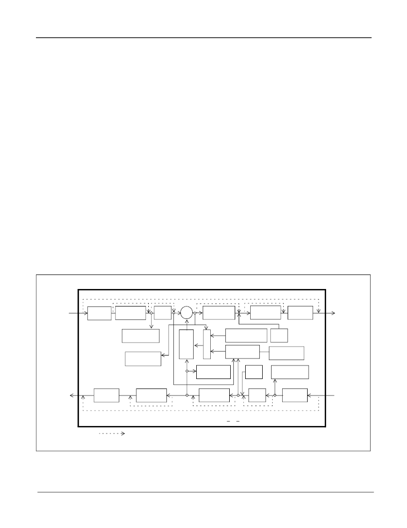
Each Echo Voice Processor contains the following main elements (see Figure 4).
Each echo canceller in the EVP has four functional states: Mute, Bypass, Disable Adaptation and Enable Adaptation.
These are explained in the section entitled Echo Canceller Functional States.
Adaptive Filter for estimating the echo channel
Subtractor for cancelling the echo
Double-Talk detector for disabling the filter adaptation during periods of double-talk
Path Change detector for fast reconvergence on major echo path changes
Instability Detector to combat instability in very low ERL environments
Patented Advanced Non-Linear Processor for suppression of residual echo, with comfort noise injection
Disable Tone Detectors for detecting valid disable tones at send and receive path inputs
Narrow-Band Detector for preventing Adaptive Filter divergence from narrow-band signals
Offset Null filters for removing the DC component in PCM channels
0 to -12dB level adjusters at all signal ports
Parallel controller interface compatible with Motorola microcontrollers
PCM encoder/decoder compatible with
μ
/A-Law ITU-T G.711 or Sign-Magnitude coding
Figure 4 - Functional Block Diagram of an Echo Canceller
Σ
Non-Linear
Processor
Offset
Null
Linear/
μ
/A-Law
Microprocessor
Interface
Double - Talk
Detector
C
Narrow-Band
Detector
μ
/A-Law/
Linear
Offset
Null
Echo Canceller (N), where 0 < N < 31
Sout
Rin
Sin
Rout
-
Programmable Bypass
(channel N)
(channel N)
(channel N)
(channel N)
ST-BUS
PORT1
ST-BUS
PORT2
MuteR
MuteS
0 to -12dB
Level Adjust
Linear/
μ
/A-Law
0 to -12dB
Level Adjust
0 to -12dB
Level Adjust
μ
/A-Law/
Linear
0 to -12dB
Level Adjust
A
F
Disable Tone
Detector
Disable Tone
Detector
Detector
Path Change
Instability
Detector
相關(guān)PDF資料 |
PDF描述 |
|---|---|
| ZL50232GDC | 32 Channel Voice Echo Canceller |
| ZL50232QCC | Aluminum Electrolytic Capacitor; Capacitor Type:General Purpose; Voltage Rating:35VDC; Capacitor Dielectric Material:Aluminum Electrolytic; Operating Temperature Range:-40 C to +85 C; Capacitance:47uF RoHS Compliant: Yes |
| ZL50232QCC1 | 32 Channel Voice Echo Canceller |
| ZL50232 | 32 Channel Voice Echo Canceller |
| ZL50233GD | 4 Channel Voice Echo Cancellor |
相關(guān)代理商/技術(shù)參數(shù) |
參數(shù)描述 |
|---|---|
| ZL50212/GBC | 制造商:Microsemi Corporation 功能描述:ECHO CANCELLER CHIP 288CH G.164/G.165/G.168/G.711 W/ TONE DE - Trays |
| ZL50212GB | 制造商:未知廠家 制造商全稱:未知廠家 功能描述:Telecomm/Datacomm |
| ZL50232 | 制造商:ZARLINK 制造商全稱:Zarlink Semiconductor Inc 功能描述:32 Channel Voice Echo Canceller |
| ZL50232/GDC | 制造商:Microsemi Corporation 功能描述:ECHO CANCELLER CHIP 32CH G.164/G.165/G.168/G.711 W/ TONE DET - Trays |
| ZL50232/QCC | 制造商:Microsemi Corporation 功能描述:ECHO CANCELLER CHIP 32CH G.164/G.165/G.168/G.711 W/ TONE DET - Trays |
發(fā)布緊急采購,3分鐘左右您將得到回復(fù)。