- 您現(xiàn)在的位置:買賣IC網(wǎng) > PDF目錄373786 > ZL50212 (Zarlink Semiconductor Inc.) 288 Channel Voice Echo Canceller PDF資料下載
參數(shù)資料
| 型號(hào): | ZL50212 |
| 廠商: | Zarlink Semiconductor Inc. |
| 英文描述: | 288 Channel Voice Echo Canceller |
| 中文描述: | 288頻道語(yǔ)音回聲消除器 |
| 文件頁(yè)數(shù): | 20/43頁(yè) |
| 文件大?。?/td> | 2166K |
| 代理商: | ZL50212 |
第1頁(yè)第2頁(yè)第3頁(yè)第4頁(yè)第5頁(yè)第6頁(yè)第7頁(yè)第8頁(yè)第9頁(yè)第10頁(yè)第11頁(yè)第12頁(yè)第13頁(yè)第14頁(yè)第15頁(yè)第16頁(yè)第17頁(yè)第18頁(yè)第19頁(yè)當(dāng)前第20頁(yè)第21頁(yè)第22頁(yè)第23頁(yè)第24頁(yè)第25頁(yè)第26頁(yè)第27頁(yè)第28頁(yè)第29頁(yè)第30頁(yè)第31頁(yè)第32頁(yè)第33頁(yè)第34頁(yè)第35頁(yè)第36頁(yè)第37頁(yè)第38頁(yè)第39頁(yè)第40頁(yè)第41頁(yè)第42頁(yè)第43頁(yè)
ZL50212
Data Sheet
20
Zarlink Semiconductor Inc.
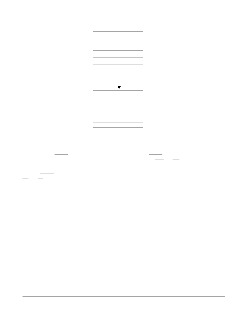
Figure 10 - Memory Mapping
7.4
Power Up Sequence
On power up, the RESET pin must be held low for 100
μ
s. Forcing the RESET pin low will put each EVP in power
down state. In this state, all internal clocks are halted, D<7:0>, Sout, Rout, DTA and IRQ pins are tristated. The 16
Main Control Registers, the Interrupt FIFO Register and the Test Register are reset to zero.
When the RESET pin returns to logic high and a valid MCLK is applied, the user must wait 500
μ
s for the PLL to lock.
C4i and F0i can be active during this period. Once the PLL has locked, the user must power up the 16 groups of
echo cancellers individually, by writing a “1” into the PWUP bit in each group of echo canceller’s Main Control
Register.
For each group of echo cancellers, when the PWUP bit toggles from zero to one, echo cancellers A and B execute
their initialization routine. The initialization routine sets their registers, Base Address+00
hex
to Base Address+3F
hex
,
to the default power-up value and clears the Adaptive Filter coefficients. Two frames are necessary for the
initialization routine to execute properly.
Once the initialization routine is executed, the user can set the per channel Control Registers, Base Address+00
hex
to Base Address+3F
hex
, for the specific application.
7.5
Power management
Each group of echo cancellers can be placed in Power Down mode by writing a “0” into the PWUP bit in their
respective Main Control Register. When a given group is in Power Down mode, the corresponding PCM data are
bypassed from Rin to Rout and from Sin to Sout with two frames delay. Refer to the Main Control Register section
for description.
The typical power consumption can be calculated with the following equation:
P
C
= 9 * Nb_of_groups + 3.6, in mW
where 0
≤
Nb_of_groups
≤
16.
0000h -->
Channel 0, ECA Ctrl/Stat Registers
001Fh
0020h -->
Channel 1, ECB Ctrl/Stat Registers
003Fh
0040h -->
Channel 2, ECA Ctrl/Stat Registers
005Fh
0060h -->
Channel 3, ECB Ctrl/Stat Registers
007Fh
03C0h -->
Channel 30, ECA Ctrl/Stat Registers
03DFh
03E0h -->
Channel 31, ECB Ctrl/Stat Registers
03FFh
0400h --> 040Fh
Main Control Registers <15:0>
Group 0
Echo
Cancellers
Registers
Groups 2 --> 14
Echo Cancellers
Registers
Group 1
Echo
Cancellers
Registers
Group 15
Echo
Cancellers
Registers
0410h
Interrupt FIFO Register
0411h
Test Register
0412h ---> FFFFh
Reserved Test Register
相關(guān)PDF資料 |
PDF描述 |
|---|---|
| ZL50232GDC | 32 Channel Voice Echo Canceller |
| ZL50232QCC | Aluminum Electrolytic Capacitor; Capacitor Type:General Purpose; Voltage Rating:35VDC; Capacitor Dielectric Material:Aluminum Electrolytic; Operating Temperature Range:-40 C to +85 C; Capacitance:47uF RoHS Compliant: Yes |
| ZL50232QCC1 | 32 Channel Voice Echo Canceller |
| ZL50232 | 32 Channel Voice Echo Canceller |
| ZL50233GD | 4 Channel Voice Echo Cancellor |
相關(guān)代理商/技術(shù)參數(shù) |
參數(shù)描述 |
|---|---|
| ZL50212/GBC | 制造商:Microsemi Corporation 功能描述:ECHO CANCELLER CHIP 288CH G.164/G.165/G.168/G.711 W/ TONE DE - Trays |
| ZL50212GB | 制造商:未知廠家 制造商全稱:未知廠家 功能描述:Telecomm/Datacomm |
| ZL50232 | 制造商:ZARLINK 制造商全稱:Zarlink Semiconductor Inc 功能描述:32 Channel Voice Echo Canceller |
| ZL50232/GDC | 制造商:Microsemi Corporation 功能描述:ECHO CANCELLER CHIP 32CH G.164/G.165/G.168/G.711 W/ TONE DET - Trays |
| ZL50232/QCC | 制造商:Microsemi Corporation 功能描述:ECHO CANCELLER CHIP 32CH G.164/G.165/G.168/G.711 W/ TONE DET - Trays |
發(fā)布緊急采購(gòu),3分鐘左右您將得到回復(fù)。