- 您現(xiàn)在的位置:買賣IC網(wǎng) > PDF目錄1976 > XR20V2170IL40-F (Exar Corporation)IC UART/TXRX I2C/SPI RS232 40QFN PDF資料下載
參數(shù)資料
| 型號: | XR20V2170IL40-F |
| 廠商: | Exar Corporation |
| 文件頁數(shù): | 14/49頁 |
| 文件大小: | 0K |
| 描述: | IC UART/TXRX I2C/SPI RS232 40QFN |
| 標(biāo)準(zhǔn)包裝: | 490 |
| 特點: | * |
| 通道數(shù): | 1,UART |
| FIFO's: | 64 字節(jié) |
| 規(guī)程: | RS232 |
| 電源電壓: | 2.97 V ~ 3.63 V |
| 帶自動流量控制功能: | 是 |
| 帶故障啟動位檢測功能: | 是 |
| 帶調(diào)制解調(diào)器控制功能: | 是 |
| 帶CMOS: | 是 |
| 安裝類型: | 表面貼裝 |
| 封裝/外殼: | 40-VFQFN 裸露焊盤 |
| 供應(yīng)商設(shè)備封裝: | 40-QFN 裸露焊盤(6x6) |
| 包裝: | 托盤 |
| 其它名稱: | 1016-1478 XR20V2170IL40-F-ND |
第1頁第2頁第3頁第4頁第5頁第6頁第7頁第8頁第9頁第10頁第11頁第12頁第13頁當(dāng)前第14頁第15頁第16頁第17頁第18頁第19頁第20頁第21頁第22頁第23頁第24頁第25頁第26頁第27頁第28頁第29頁第30頁第31頁第32頁第33頁第34頁第35頁第36頁第37頁第38頁第39頁第40頁第41頁第42頁第43頁第44頁第45頁第46頁第47頁第48頁第49頁
XR20V2170
21
REV. 1.0.1
I2C/SPI UART WITH 64-BYTE FIFO AND RS232 TRANSCEIVER
4.0 INTERNAL REGISTER DESCRIPTIONS
4.1
Receive Holding Register (RHR) - Read- Only
4.2
Transmit Holding Register (THR) - Write-Only
4.3
Interrupt Enable Register (IER) - Read/Write
The Interrupt Enable Register (IER) masks the interrupts from receive data ready, transmit empty, line status
and modem status registers. These interrupts are reported in the Interrupt Status Register (ISR).
0x0A
IODir
RD/WR
0
1
0
Bit-3
Bit-2
Bit-1
Bit-0
0x0B
IOState RD/WR
0
Bit-3
Bit-2
Bit-1
Bit-0
0x0C IOIntEna RD/WR
0
Bit-3
Bit-2
Bit-1
Bit-0
0x0D reserved
-
0
0x0E IOControl RD/WR
0
UART
SW
Reset
0
1
IOLatch
0x0F
EFCR
RD/WR
0
TX
Disable
RX
Disable
0
Baud Rate Generator Divisor
0x00
DLL
RD/WR
Bit-7
Bit-6
Bit-5
Bit-4
Bit-3
Bit-2
Bit-1
Bit-0
LCR[7]=1
LCR
≠0xBF
0x01
DLM
RD/WR
Bit-7
Bit-6
Bit-5
Bit-4
Bit-3
Bit-2
Bit-1
Bit-0
0x02
DLD
RD/WR
Bit-7
Bit-6
4X
Mode
8X Mode
Frac-
tional
Divisor
Bit-3
Frac-
tional
Divisor
Bit-2
Frac-
tional
Divisor
Bit-1
Frac-
tional
Divisor
Bit-0
LCR[7]=1
LCR
≠0xBF
EFR[4]=1
Enhanced Registers
0x02
EFR
RD/WR
Auto
CTS
Enable
Auto RTS
Enable
Special
Char
Select
Enable
IER [7:4],
ISR [5:4],
FCR[5:4],
MCR[7:5],
DLD
Soft-
ware
Flow
Cntl
Bit-3
Soft-
ware
Flow
Cntl
Bit-2
Soft-
ware
Flow
Cntl
Bit-1
Soft-
ware
Flow
Cntl
Bit-0
LCR=0XBF
0x04
XON1
RD/WR
Bit-7
Bit-6
Bit-5
Bit-4
Bit-3
Bit-2
Bit-1
Bit-0
0x05
XON2
RD/WR
Bit-7
Bit-6
Bit-5
Bit-4
Bit-3
Bit-2
Bit-1
Bit-0
0x06
XOFF1
RD/WR
Bit-7
Bit-6
Bit-5
Bit-4
Bit-3
Bit-2
Bit-1
Bit-0
0x07
XOFF2
RD/WR
Bit-7
Bit-6
Bit-5
Bit-4
Bit-3
Bit-2
Bit-1
Bit-0
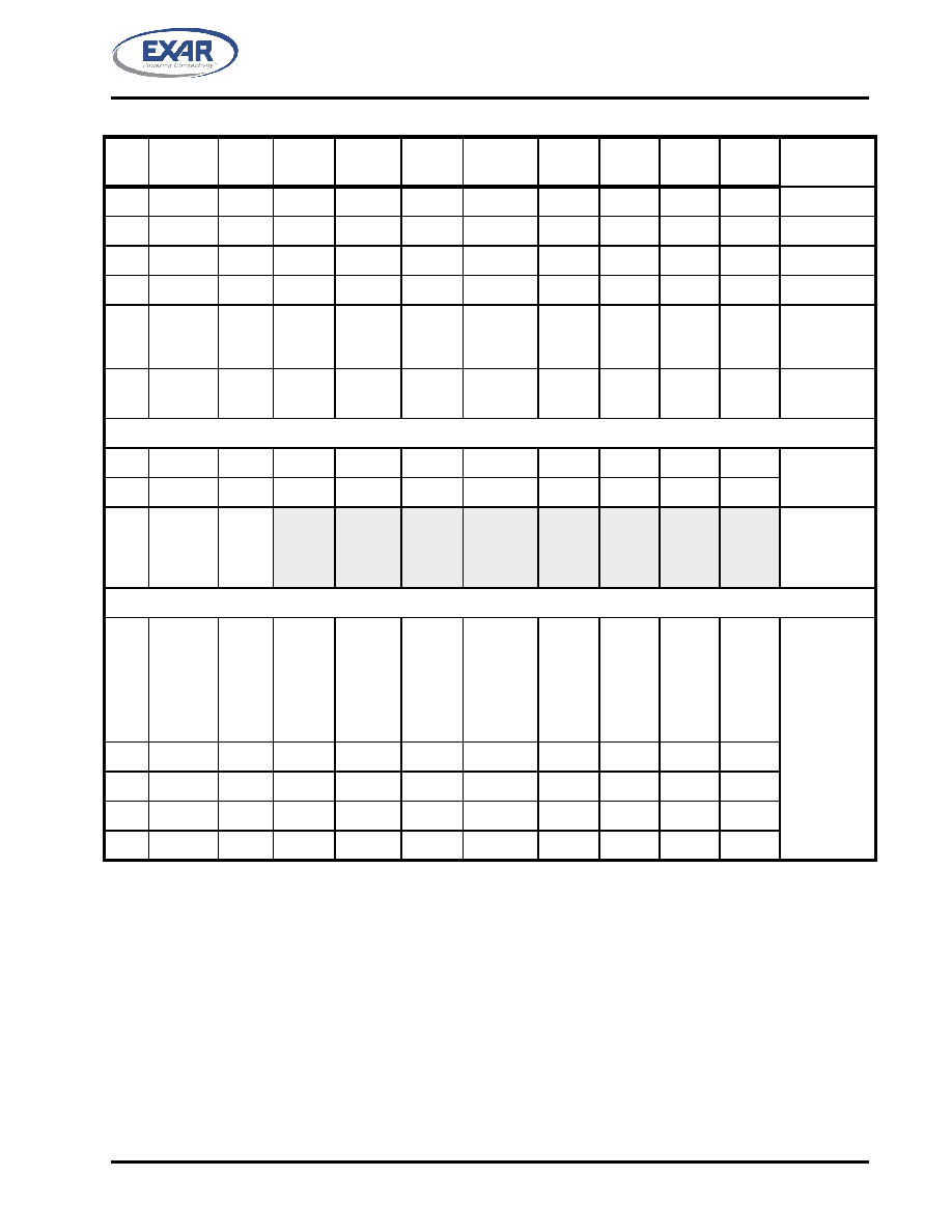
TABLE 8: INTERNAL REGISTERS DESCRIPTION. SHADED BITS ARE ENABLED WHEN EFR BIT-4=1
ADDR
REG
NAME
READ/
WRITE
BIT-7
BIT-6
BIT-5
BIT-4
BIT-3
BIT-2
BIT-1
BIT-0
COMMENT
相關(guān)PDF資料 |
PDF描述 |
|---|---|
| XR20V2172IL64-F | IC UART/TXRX I2C/SPI RS232 64QFN |
| XR21V1410IL16TR-F | IC USB UART FIFO FULL SPD 16QFN |
| XR21V1412IL32TR-F | IC USB UART FIFO FULL SPD 32QFN |
| XR21V1414IM48-F | IC UART FIFO USB QUAD 48TQFP |
| XR3178EID-F | IC TXRX RS485 DIFF 3V 8NSOIC |
相關(guān)代理商/技術(shù)參數(shù) |
參數(shù)描述 |
|---|---|
| XR20V2170L40-0A-EB | 功能描述:界面開發(fā)工具 Supports V2170 40pin QFN,I2C Interface RoHS:否 制造商:Bourns 產(chǎn)品:Evaluation Boards 類型:RS-485 工具用于評估:ADM3485E 接口類型:RS-485 工作電源電壓:3.3 V |
| XR20V2170L40-0B-EB | 功能描述:UART 接口集成電路 Supports V2170 40pin QFN,SPI Interface RoHS:否 制造商:Texas Instruments 通道數(shù)量:2 數(shù)據(jù)速率:3 Mbps 電源電壓-最大:3.6 V 電源電壓-最小:2.7 V 電源電流:20 mA 最大工作溫度:+ 85 C 最小工作溫度:- 40 C 封裝 / 箱體:LQFP-48 封裝:Reel |
| XR20V2172 | 制造商:EXAR 制造商全稱:EXAR 功能描述:TWO CHANNEL I2C/SPI UART WITH 64-BYTE FIFO AND RS232 TRANSCEIVER |
| XR20V2172_08 | 制造商:EXAR 制造商全稱:EXAR 功能描述:TWO CHANNEL I2C/SPI UART WITH 64-BYTE FIFO AND RS232 TRANSCEIVER |
| XR20V2172IL64 | 制造商:EXAR 制造商全稱:EXAR 功能描述:TWO CHANNEL I2C/SPI UART WITH 64-BYTE FIFO AND RS232 TRANSCEIVER |
發(fā)布緊急采購,3分鐘左右您將得到回復(fù)。