- 您現(xiàn)在的位置:買賣IC網(wǎng) > PDF目錄4058 > XCS30-3BG256C (Xilinx Inc)IC FPGA 5V C-TEMP 256-PBGA PDF資料下載
參數(shù)資料
| 型號(hào): | XCS30-3BG256C |
| 廠商: | Xilinx Inc |
| 文件頁數(shù): | 47/83頁 |
| 文件大小: | 0K |
| 描述: | IC FPGA 5V C-TEMP 256-PBGA |
| 標(biāo)準(zhǔn)包裝: | 40 |
| 系列: | Spartan® |
| LAB/CLB數(shù): | 576 |
| 邏輯元件/單元數(shù): | 1368 |
| RAM 位總計(jì): | 18432 |
| 輸入/輸出數(shù): | 192 |
| 門數(shù): | 30000 |
| 電源電壓: | 4.75 V ~ 5.25 V |
| 安裝類型: | 表面貼裝 |
| 工作溫度: | 0°C ~ 85°C |
| 封裝/外殼: | 256-BBGA |
| 供應(yīng)商設(shè)備封裝: | 256-PBGA |
第1頁第2頁第3頁第4頁第5頁第6頁第7頁第8頁第9頁第10頁第11頁第12頁第13頁第14頁第15頁第16頁第17頁第18頁第19頁第20頁第21頁第22頁第23頁第24頁第25頁第26頁第27頁第28頁第29頁第30頁第31頁第32頁第33頁第34頁第35頁第36頁第37頁第38頁第39頁第40頁第41頁第42頁第43頁第44頁第45頁第46頁當(dāng)前第47頁第48頁第49頁第50頁第51頁第52頁第53頁第54頁第55頁第56頁第57頁第58頁第59頁第60頁第61頁第62頁第63頁第64頁第65頁第66頁第67頁第68頁第69頁第70頁第71頁第72頁第73頁第74頁第75頁第76頁第77頁第78頁第79頁第80頁第81頁第82頁第83頁

Spartan and Spartan-XL FPGA Families Data Sheet
DS060 (v2.0) March 1, 2013
51
Product Specification
R
Product Obsolete/Under Obsolescence
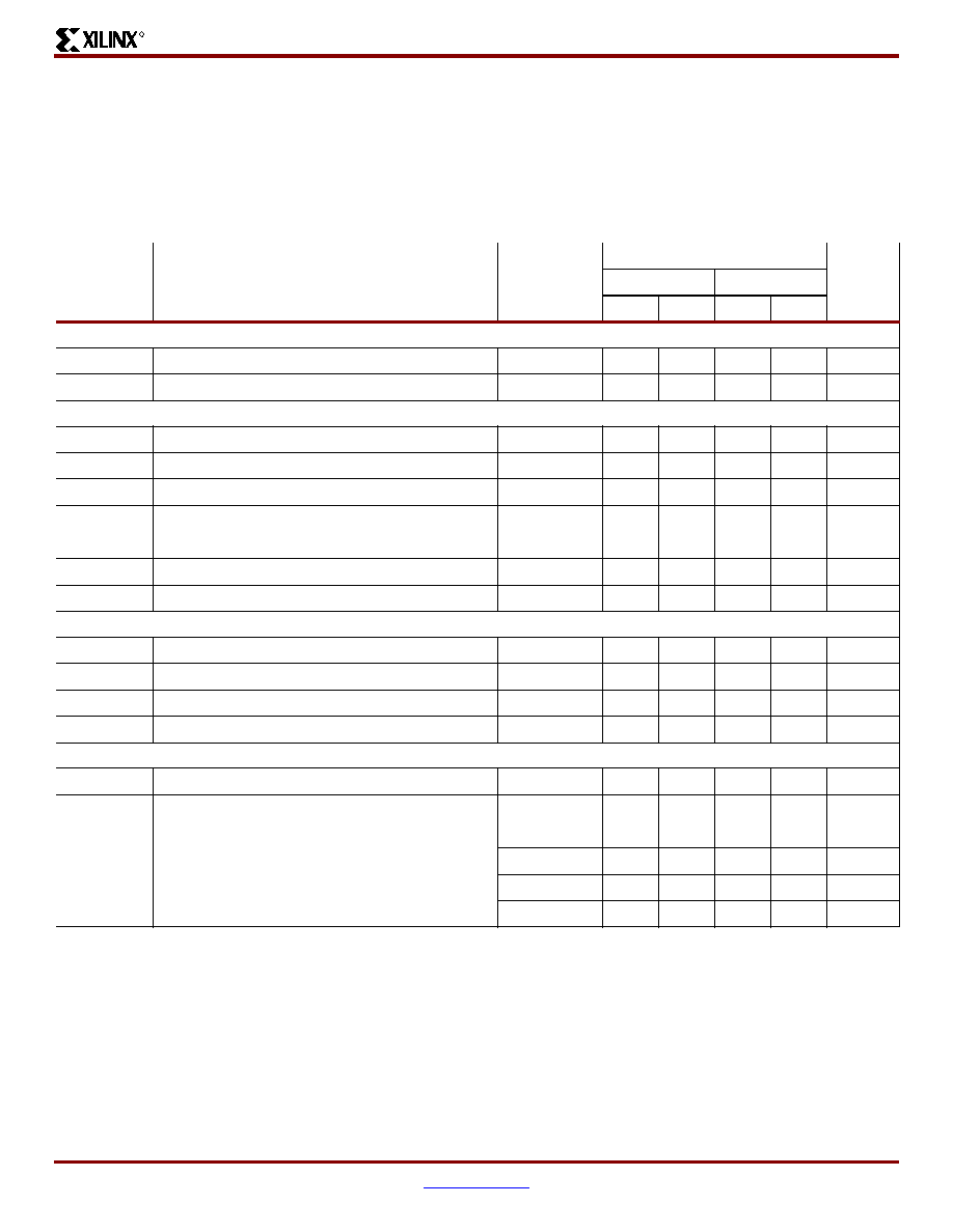
Spartan Family IOB Output Switching Characteristic Guidelines
All devices are 100% functionally tested. Internal timing
parameters are derived from measuring internal test pat-
terns. Listed below are representative values. For more
specific, more precise, and worst-case guaranteed data,
use the values reported by the static timing analyzer (TRCE
in the Xilinx Development System) and back-annotated to
the simulation netlist. These path delays, provided as a
guideline, have been extracted from the static timing ana-
lyzer report. All timing parameters assume worst-case oper-
ating conditions (supply voltage and junction temperature).
Values are expressed in nanoseconds unless otherwise
noted.
Symbol
Description
Device
Speed Grade
Units
-4
-3
Min
Max
Min
Max
Clocks
TCH
Clock High
All devices
3.0
-
4.0
-
ns
TCL
Clock Low
All devices
3.0
-
4.0
-
ns
Propagation Delays - TTL Outputs(1,2)
TOKPOF
Clock (OK) to Pad, fast
All devices
-
3.3
-
4.5
ns
TOKPOS
Clock (OK to Pad, slew-rate limited
All devices
-
6.9
-
7.0
ns
TOPF
Output (O) to Pad, fast
All devices
-
3.6
-
4.8
ns
TOPS
Output (O) to Pad, slew-rate limited
All devices
-
7.2
-
7.3
ns
TTSHZ
3-state to Pad High-Z (slew-rate independent)
All devices
-
3.0
-
3.8
ns
TTSONF
3-state to Pad active and valid, fast
All devices
-
6.0
-
7.3
ns
TTSONS
3-state to Pad active and valid, slew-rate limited
All devices
-
9.6
-
9.8
ns
Setup and Hold Times
TOOK
Output (O) to clock (OK) setup time
All devices
2.5
-
3.8
-
ns
TOKO
Output (O) to clock (OK) hold time
All devices
0.0
-
0.0
-
ns
TECOK
Clock Enable (EC) to clock (OK) setup time
All devices
2.0
-
2.7
-
ns
TOKEC
Clock Enable (EC) to clock (OK) hold time
All devices
0.0
-
0.5
-
ns
Global Set/Reset
TMRW
Minimum GSR pulse width
All devices
11.5
13.5
ns
TRPO
Delay from GSR input to any Pad
XCS05
-
12.0
-
15.0
ns
XCS10
-
12.5
-
15.7
ns
XCS20
-
13.0
-
16.2
ns
XCS30
-
13.5
-
16.9
ns
XCS40
-
14.0
-
17.5
ns
Notes:
1.
Delay adder for CMOS Outputs option (with fast slew rate option): for -3 speed grade, add 1.0 ns; for -4 speed grade, add 0.8 ns.
2.
Delay adder for CMOS Outputs option (with slow slew rate option): for -3 speed grade, add 2.0 ns; for -4 speed grade, add 1.5 ns.
3.
Output timing is measured at ~50% VCC threshold, with 50 pF external capacitive loads including test fixture. Slew-rate limited output
rise/fall times are approximately two times longer than fast output rise/fall times.
4.
Voltage levels of unused pads, bonded or unbonded, must be valid logic levels. Each can be configured with the internal pull-up
(default) or pull-down resistor, or configured as a driven output, or can be driven from an external source.
相關(guān)PDF資料 |
PDF描述 |
|---|---|
| MPC860PVR80D4R2 | IC MPU POWERQUICC 80MHZ 357PBGA |
| IDT71T75602S133BG8 | IC SRAM 18MBIT 133MHZ 119BGA |
| IDT71T75602S100BGG8 | IC SRAM 18MBIT 100MHZ 119BGA |
| IDT71T75602S100BG8 | IC SRAM 18MBIT 100MHZ 119BGA |
| IDT71V67803S166PFG | IC SRAM 9MBIT 166MHZ 100TQFP |
相關(guān)代理商/技術(shù)參數(shù) |
參數(shù)描述 |
|---|---|
| XCS30-3BG256I | 制造商:XILINX 制造商全稱:XILINX 功能描述:Spartan and Spartan-XL Families Field Programmable Gate Arrays |
| XCS30-3BG280C | 制造商:XILINX 制造商全稱:XILINX 功能描述:Spartan and Spartan-XL Families Field Programmable Gate Arrays |
| XCS30-3BG280I | 制造商:XILINX 制造商全稱:XILINX 功能描述:Spartan and Spartan-XL Families Field Programmable Gate Arrays |
| XCS30-3BG84C | 制造商:XILINX 制造商全稱:XILINX 功能描述:Spartan and Spartan-XL Families Field Programmable Gate Arrays |
| XCS30-3BG84I | 制造商:XILINX 制造商全稱:XILINX 功能描述:Spartan and Spartan-XL Families Field Programmable Gate Arrays |
發(fā)布緊急采購,3分鐘左右您將得到回復(fù)。