- 您現(xiàn)在的位置:買賣IC網 > PDF目錄300104 > WE904 (Electronic Theatre Controls, Inc.) 0.1 - 1GHx Single Chip FM Transceiver PDF資料下載
參數資料
| 型號: | WE904 |
| 廠商: | Electronic Theatre Controls, Inc. |
| 英文描述: | 0.1 - 1GHx Single Chip FM Transceiver |
| 中文描述: | 0.1 - 1GHx單芯片F(xiàn)M收發(fā)器 |
| 文件頁數: | 28/39頁 |
| 文件大?。?/td> | 623K |
| 代理商: | WE904 |
第1頁第2頁第3頁第4頁第5頁第6頁第7頁第8頁第9頁第10頁第11頁第12頁第13頁第14頁第15頁第16頁第17頁第18頁第19頁第20頁第21頁第22頁第23頁第24頁第25頁第26頁第27頁當前第28頁第29頁第30頁第31頁第32頁第33頁第34頁第35頁第36頁第37頁第38頁第39頁
Winceiver WE904/WE905
WiNEDGE & WiRELESS
0.1 - 1GHz Single Chip FM Transceiver
2003 WiNEDGE & WiRELESS PTE LTD
Page 34
Rev Date: 2003 May 27
OPERATION MODES (BIT 18-22)
In Normal Mode, the AFO output can be configured to either analog or digital mode. In the Analog
Mode, this output pin provides the recovered, demodulated audio signal. In the Digital Mode, the
demodulated signal goes through an internal data slicer before being output as CMOS compatible
logic data.
Other than Normal Mode, the device offers test modes (in both WE904 and WE905) and 2 other
special operating modes in WE905. In Test Mode, The AFO output pin can be configured to provide
signal at various stages in the receiver path for trouble-shooting purpose.
The special operating modes available on WE905 are Tx Charge Pump Disable Mode and Reference
Oscillator On Mode
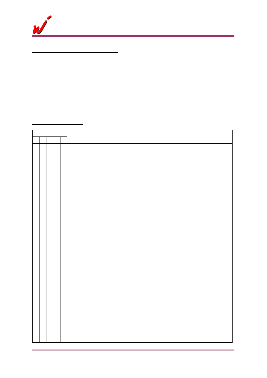
Other Modes for WE904
Mode Bits
Other Mode for WE904
5 4 3 2 1
X X 1 0 0
I Baseband Filter Test
I baseband filter output route to AUDO (analogue)
Only for Analogue output select
The I Baseband output of the Quadrature mixer is a sinusoidal waveform that
center at approx. 1.34Vdc and amplitude depends on the injected RF signal
strength.
The amplitude is about 350mVpp at -80dBm RF_IN power.
X X 1 0 1
Q Baseband Filter Test
Q baseband filter output route to AUDO (analogue)
Only for Analogue output select
The Q Baseband output of the Quadrature mixer is a sinusoidal waveform that
center at approx. 1.34Vdc and amplitude depends on the injected RF signal
strength.
The amplitude is about 350mVpp at -80dBm RF_IN power.
X X 1 1 0
2
nd Mixer Test
2
nd mixer output route to AUDO (analogue)
Only for Analogue output select
The 2nd mixer output is a sinusoidal waveform at frequency
Fif (= Frf / PDR / 544) +/- FM Dev.
The amplitude is about 280mVpp at -80dBm RF_IN power.
X X 1 1 1
IF Filter Test: (analogue)
Input to IF filter via AFCC, filter output route to AUDO. Only for Analogue output
select. AFC disabled.
Input a 1.3Vdc + 500mVpp sinusoidal signal to IF filter via AFCC pin 47. All
components connected to pin 47 are removed to prevent loading. Response of
IF low pass filter can be observed at AFO.
Example: IFSET resistor = 22kohm, upper 3dB corner frequency should be at
about 206kHz.
相關PDF資料 |
PDF描述 |
|---|---|
| WE905 | 0.1 - 1GHx Single Chip FM Transceiver |
| WED2DG472512V65D2 | 2M X 72 MULTI DEVICE SRAM MODULE, 3.7 ns, DMA168 |
| WED3DG64128V10D1 | 128M X 64 SYNCHRONOUS DRAM MODULE, DMA144 |
| WED3DG64128V75D1 | 128M X 64 SYNCHRONOUS DRAM MODULE, DMA144 |
| WED3EG6417S262D4 | 16M X 64 DDR DRAM MODULE, DMA200 |
相關代理商/技術參數 |
參數描述 |
|---|---|
| WE905 | 制造商:未知廠家 制造商全稱:未知廠家 功能描述:0.1 - 1GHx Single Chip FM Transceiver |
| WE9104 | 制造商:未知廠家 制造商全稱:未知廠家 功能描述:Pulse Telephone Dialer |
| WE9110 | 制造商:未知廠家 制造商全稱:未知廠家 功能描述:Pulse Telephone Dialer |
| WE9140 | 制造商:WINBOND 制造商全稱:Winbond 功能描述:TONE/PULSE SWITCHABLE DIALER WITH REDIAL |
| WE9140A | 制造商:WINBOND 制造商全稱:Winbond 功能描述:TONE/PULSE SWITCHABLE DIALER WITH REDIAL |
發(fā)布緊急采購,3分鐘左右您將得到回復。