- 您現(xiàn)在的位置:買賣IC網(wǎng) > PDF目錄300104 > WE904 (Electronic Theatre Controls, Inc.) 0.1 - 1GHx Single Chip FM Transceiver PDF資料下載
參數(shù)資料
| 型號: | WE904 |
| 廠商: | Electronic Theatre Controls, Inc. |
| 英文描述: | 0.1 - 1GHx Single Chip FM Transceiver |
| 中文描述: | 0.1 - 1GHx單芯片F(xiàn)M收發(fā)器 |
| 文件頁數(shù): | 11/39頁 |
| 文件大小: | 623K |
| 代理商: | WE904 |
第1頁第2頁第3頁第4頁第5頁第6頁第7頁第8頁第9頁第10頁當前第11頁第12頁第13頁第14頁第15頁第16頁第17頁第18頁第19頁第20頁第21頁第22頁第23頁第24頁第25頁第26頁第27頁第28頁第29頁第30頁第31頁第32頁第33頁第34頁第35頁第36頁第37頁第38頁第39頁
Winceiver WE904/WE905
WiNEDGE & WiRELESS
0.1 - 1GHz Single Chip FM Transceiver
2003 WiNEDGE & WiRELESS PTE LTD
Page 19
Rev Date: 2003 May 27
If non-volatile memory (EEPROM or flash) is available, correction can be done during production
testing. The ADC can read RSSI values at no signal and at a know Rx signal level, and store those
values to correct for the RSSI tolerance.
If non-volatile memory (EEPROM or flash) is not available, correct can be done by checking and
remember, in the RAM, the RSSI value with no Rx signal, such as when LNA is off; or when antenna
switch is off at Rx side; or when Rx frequency is set to an impossible frequency.
If comparator is used, the tolerance can be corrected by adjust a trimmer pot meter.
RSSI SETTLING TIME
For 130kHz Rx bandwidth, ~25kHz FM deviation, and with recommended 10nF external capacitor
attached to RSSI pin, the RSSI reaches 80% of its final value in approximately 0.5ms.
If the FM signal carried is varying significantly in amplitude (e.g. FSK, switching between FM deviation
limits) then a longer integration time (i.e. larger RSSI capacitor) will be required for accurate
measurement of RX signal strength. Hence, settling time will be longer.
Also, for a narrower Rx bandwidth, the capacitor should be increased to integrate the received power
over a longer time. The increase should be inverse proportional to the bandwidth. RSSI response time
will also increase accordingly.
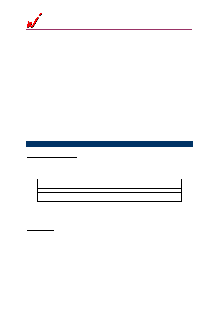
RX/TX RESPONSE TIME
RX/TX PLL LOCK TIME
The values shown below are based upon calculations using the component values shown in
application circuit with Rx and Tx charge pump currents being 1.0mA and 0.2mA respectively; and
reference frequency being 100kHz.
Frequency
Rx
Tx
From start up
8.5 ms
17 ms
10MHz frequency change
6.5 ms
14 ms
1.0MHz frequency change
5.0 ms
11 ms
0.1MHz frequency change
3.5 ms
7 ms
Note: The settling time for Tx are based upon a 150 Hz high pass filter (HPF) cut off frequency. This
filter can be adjusted via the external Tx PLL loop filter components, or by the on-chip Tx charge
pump current selection. Settling time will be approximately inversely proportional to the required HPF
for the audio/data signal.
PLL Loop Filter
Faster PLL lock times are required in applications where time division duplexing or frequency hopping
techniques is used. On the contrary, narrow band audio applications, which need low VCO phase
noise, require tightening of PLL loop filter bandwidth. In the result, increases PLL lock time.
The loop filters employed are second order passive loop filters. Separate literatures are available for
various filter response considerations and calculation of filter components. Dumping factor, phase
noise and reference spurs are the main considerations beside lock time.
The following information is required for designing the PLL loop filter:
Kvco
相關(guān)PDF資料 |
PDF描述 |
|---|---|
| WE905 | 0.1 - 1GHx Single Chip FM Transceiver |
| WED2DG472512V65D2 | 2M X 72 MULTI DEVICE SRAM MODULE, 3.7 ns, DMA168 |
| WED3DG64128V10D1 | 128M X 64 SYNCHRONOUS DRAM MODULE, DMA144 |
| WED3DG64128V75D1 | 128M X 64 SYNCHRONOUS DRAM MODULE, DMA144 |
| WED3EG6417S262D4 | 16M X 64 DDR DRAM MODULE, DMA200 |
相關(guān)代理商/技術(shù)參數(shù) |
參數(shù)描述 |
|---|---|
| WE905 | 制造商:未知廠家 制造商全稱:未知廠家 功能描述:0.1 - 1GHx Single Chip FM Transceiver |
| WE9104 | 制造商:未知廠家 制造商全稱:未知廠家 功能描述:Pulse Telephone Dialer |
| WE9110 | 制造商:未知廠家 制造商全稱:未知廠家 功能描述:Pulse Telephone Dialer |
| WE9140 | 制造商:WINBOND 制造商全稱:Winbond 功能描述:TONE/PULSE SWITCHABLE DIALER WITH REDIAL |
| WE9140A | 制造商:WINBOND 制造商全稱:Winbond 功能描述:TONE/PULSE SWITCHABLE DIALER WITH REDIAL |
發(fā)布緊急采購,3分鐘左右您將得到回復(fù)。