- 您現(xiàn)在的位置:買賣IC網(wǎng) > PDF目錄98305 > TVP5041PFP (TEXAS INSTRUMENTS INC) COLOR SIGNAL DECODER, PQFP80 PDF資料下載
參數(shù)資料
| 型號: | TVP5041PFP |
| 廠商: | TEXAS INSTRUMENTS INC |
| 元件分類: | 顏色信號轉(zhuǎn)換 |
| 英文描述: | COLOR SIGNAL DECODER, PQFP80 |
| 封裝: | POWER, PLASTIC, TQFP-80 |
| 文件頁數(shù): | 98/106頁 |
| 文件大小: | 501K |
| 代理商: | TVP5041PFP |
第1頁第2頁第3頁第4頁第5頁第6頁第7頁第8頁第9頁第10頁第11頁第12頁第13頁第14頁第15頁第16頁第17頁第18頁第19頁第20頁第21頁第22頁第23頁第24頁第25頁第26頁第27頁第28頁第29頁第30頁第31頁第32頁第33頁第34頁第35頁第36頁第37頁第38頁第39頁第40頁第41頁第42頁第43頁第44頁第45頁第46頁第47頁第48頁第49頁第50頁第51頁第52頁第53頁第54頁第55頁第56頁第57頁第58頁第59頁第60頁第61頁第62頁第63頁第64頁第65頁第66頁第67頁第68頁第69頁第70頁第71頁第72頁第73頁第74頁第75頁第76頁第77頁第78頁第79頁第80頁第81頁第82頁第83頁第84頁第85頁第86頁第87頁第88頁第89頁第90頁第91頁第92頁第93頁第94頁第95頁第96頁第97頁當(dāng)前第98頁第99頁第100頁第101頁第102頁第103頁第104頁第105頁第106頁
2–75
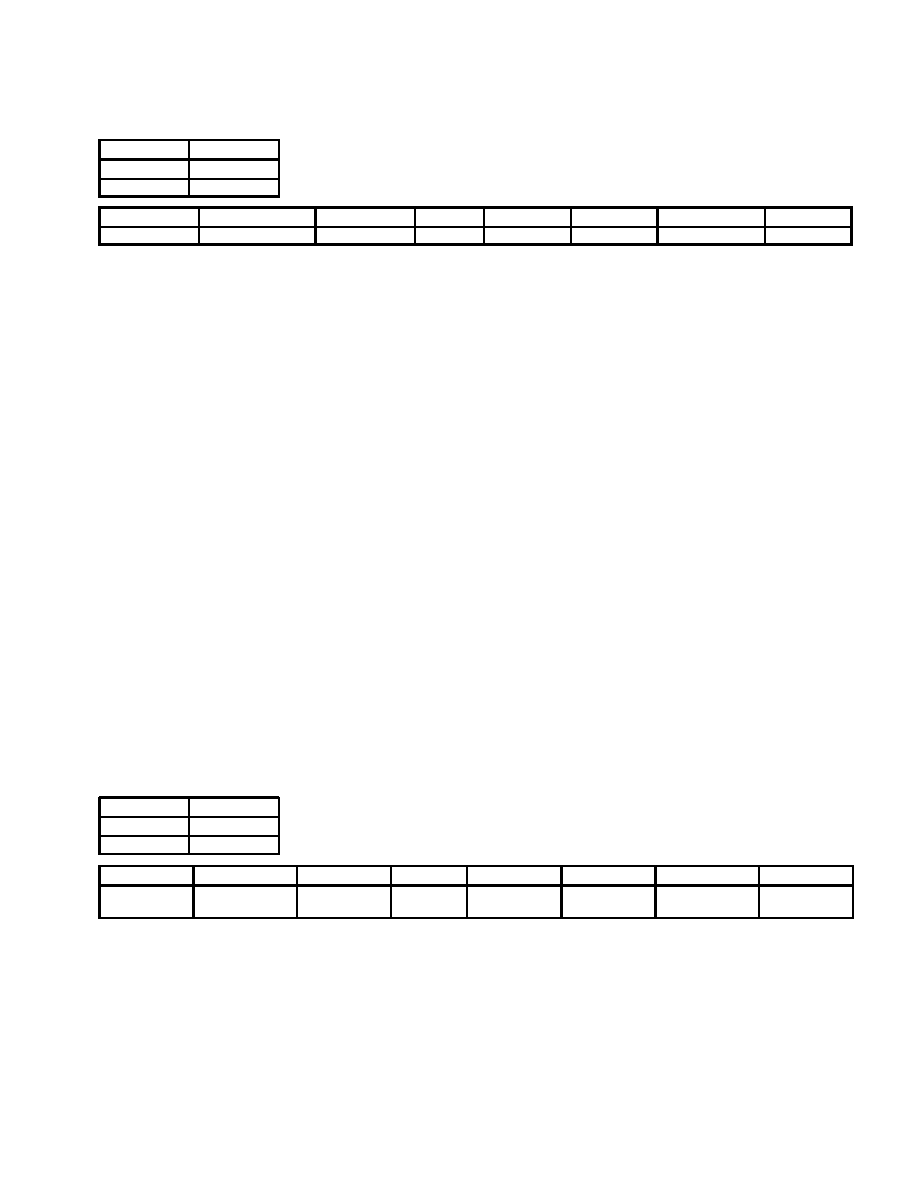
2.13.64 Interrupt Status Register A
VIP address
1C0h
PHI address
C0h
I2C address
C0h
7
6
5
4
3
2
1
0
TvpLOCK state
TvpLOCK interrupt
Cycle complete
Bus error
CC odd field
CC even field
Teletext threshold
Teletext data
tvpLOCK state
0 = TVP not locked to video (default)
1 = TVP locked to video signal
Reflects the present state of the tvpLOCK.
tvpLOCK interrupt
0 = A transition has not occurred on the tvpLOCK signal (default)
1 = A transition has occurred on the tvpLOCK signal
Note, an interrupt is generated on any transition of the Lock signal.
Cycle complete
0 = Read or write cycle in progress (default)
1 = Read or write cycle complete
Bus error
0 = No bus error (default)
1 = PHI interface detected an illegal access
CC odd field
0 = Buffer empty (default)
1 = Odd field closed caption buffer contains data
CC even field
0 = Buffer empty (default)
1 = Even field closed caption buffer contains data
Teletext threshold
0 = Threshold not reached (default)
1 = Teletext data in buffer has reached configurable threshold
Teletext data
0 = Teletext data buffer empty or the video line number has not reached the value
programmed in the interrupt line number register at address B5. (default)
1 = Teletext data buffer contains a complete transaction and the video line number =
interrupt line number
Note this bit can be configured to occur whenever the video line number = interrupt line
number register regardless of the data.
The interrupt status register A is polled by the external processor to determine the interrupt source. After an interrupt
condition is set it can be reset by writing to this register with a 1 in the appropriate bit(s).
2.13.65 Interrupt Enable Register A
VIP address
1C1h
PHI address
C1h
I2C address
C1h
7
6
5
4
3
2
1
0
tvpLOCK state
tvpLOCK
interrupt enable
Cycle complete
enable
Bus Error
Enable
CC odd field
enable
CC even field
enable
Teletext
threshold enable
Teletext data
enable
The interrupt enable register A is used by the external processor to mask unnecessary interrupt sources for interrupt
A. Bits loaded with a 1 allow the corresponding interrupt condition to generate an interrupt on the external pin.
Conversely bits loaded with a 0 mask the corresponding interrupt condition from generating an interrupt on the
external pin. Note this register only affects the interrupt A on the external terminal, it does not affect the bits in the
interrupt status register A. A given condition can set the appropriate bit in the status register and not cause an interrupt
on the external terminal. To determine if this device is driving the interrupt terminal either perform a logical AND of
the interrupt status register A with the interrupt enable register A, or check the state of the interrupt A bit in the interrupt
configuration register A.
相關(guān)PDF資料 |
PDF描述 |
|---|---|
| TVP5146M1PFP | COLOR SIGNAL DECODER, PQFP80 |
| TVP5146M2IPFPR | COLOR SIGNAL DECODER, PQFP80 |
| TVP5146M2IPFP | COLOR SIGNAL DECODER, PQFP80 |
| TVP5146M2PFPR | COLOR SIGNAL DECODER, PQFP80 |
| TVP5146M2PFP | COLOR SIGNAL DECODER, PQFP80 |
相關(guān)代理商/技術(shù)參數(shù) |
參數(shù)描述 |
|---|---|
| TVP5145 | 制造商:未知廠家 制造商全稱:未知廠家 功能描述:NTSC/PAL/SECAM/Component Digital Video Decoder With Macrovision(TM) Detection |
| TVP5145EVM | 制造商:Texas Instruments 功能描述:TVP5145EVM - Bulk |
| TVP5145PFP | 功能描述:視頻 IC NTSC/PAL/SECAM/ Comp Dig Vid Dec RoHS:否 制造商:Fairchild Semiconductor 工作電源電壓:5 V 電源電流:80 mA 最大工作溫度:+ 85 C 封裝 / 箱體:TSSOP-28 封裝:Reel |
| TVP5146 | 制造商:TI 制造商全稱:Texas Instruments 功能描述:NTSC/PAL / SECAM 4 X 10 BIT DIGITAL VIDEO DECODER WITH MACROVISION DETECTION YPBPR/RGB INPUTS 5 LINE COMB FILTER AND SCART SUPPORT |
| TVP5146_12 | 制造商:TI 制造商全稱:Texas Instruments 功能描述:NTSC/PAL/SECAM 4x10-Bit Digital Video Decoder With Macrovision?£a Detection, YPbPr/RGB Inputs, 5-Line Comb Filter, and SCART Support |
發(fā)布緊急采購,3分鐘左右您將得到回復(fù)。