- 您現(xiàn)在的位置:買賣IC網(wǎng) > PDF目錄368672 > TMS320C240PQL 16-Bit Microcontroller PDF資料下載
參數(shù)資料
| 型號(hào): | TMS320C240PQL |
| 英文描述: | 16-Bit Microcontroller |
| 中文描述: | 16位微控制器 |
| 文件頁數(shù): | 20/105頁 |
| 文件大小: | 1481K |
| 代理商: | TMS320C240PQL |
第1頁第2頁第3頁第4頁第5頁第6頁第7頁第8頁第9頁第10頁第11頁第12頁第13頁第14頁第15頁第16頁第17頁第18頁第19頁當(dāng)前第20頁第21頁第22頁第23頁第24頁第25頁第26頁第27頁第28頁第29頁第30頁第31頁第32頁第33頁第34頁第35頁第36頁第37頁第38頁第39頁第40頁第41頁第42頁第43頁第44頁第45頁第46頁第47頁第48頁第49頁第50頁第51頁第52頁第53頁第54頁第55頁第56頁第57頁第58頁第59頁第60頁第61頁第62頁第63頁第64頁第65頁第66頁第67頁第68頁第69頁第70頁第71頁第72頁第73頁第74頁第75頁第76頁第77頁第78頁第79頁第80頁第81頁第82頁第83頁第84頁第85頁第86頁第87頁第88頁第89頁第90頁第91頁第92頁第93頁第94頁第95頁第96頁第97頁第98頁第99頁第100頁第101頁第102頁第103頁第104頁第105頁
TMS320C240, TMS320F240
DSP CONTROLLERS
SPRS042D – OCTOBER 1996 – REVISED NOVEMBER 1998
20
POST OFFICE BOX 1443
HOUSTON, TEXAS 77251–1443
reset (continued)
The occurrence of a reset condition causes the TMS320x240 to terminate program execution and affects
various registers and status bits. During a reset, RAM contents remain unchanged, and all control bits that are
affected by a reset are initialized to their reset state. In the case of a power-on reset, the PLL control registers
are initialized to zero. The program needs to recognize power-on resets and configure the PLL for correct
operation.
After a reset, the program can check the power-on reset flag (PORST flag, SYSSR.15), the illegal address flag
(ILLADR flag, SYSSR.12), the software reset flag (SWRST flag, SYSSR.10), and the watchdog reset flag
(WDRST flag, SYSSR.9) to determine the source of the reset. A reset does not clear these flags.
RS and PORESET must be held low until the clock signal is valid and V
CC
is within the operating range. In
addition, PORESET must be driven low when V
CC
drops below the minimum operating voltage.
hardware-generated interrupts
All the hardware interrupt lines of the DSP core are given a priority rank from 1 to 10 (1 being highest). When
more than one of these hardware interrupts is pending acknowledgment, the interrupt of highest rank gets
acknowledged first. The others are acknowledged in order after that. Of those ten lines, six are for maskable
interrupt lines (INT1–INT6) and one is for the nonmaskable interrupt (NMI) line. INT1–INT6 and NMI have the
priorities shown in Table 5.
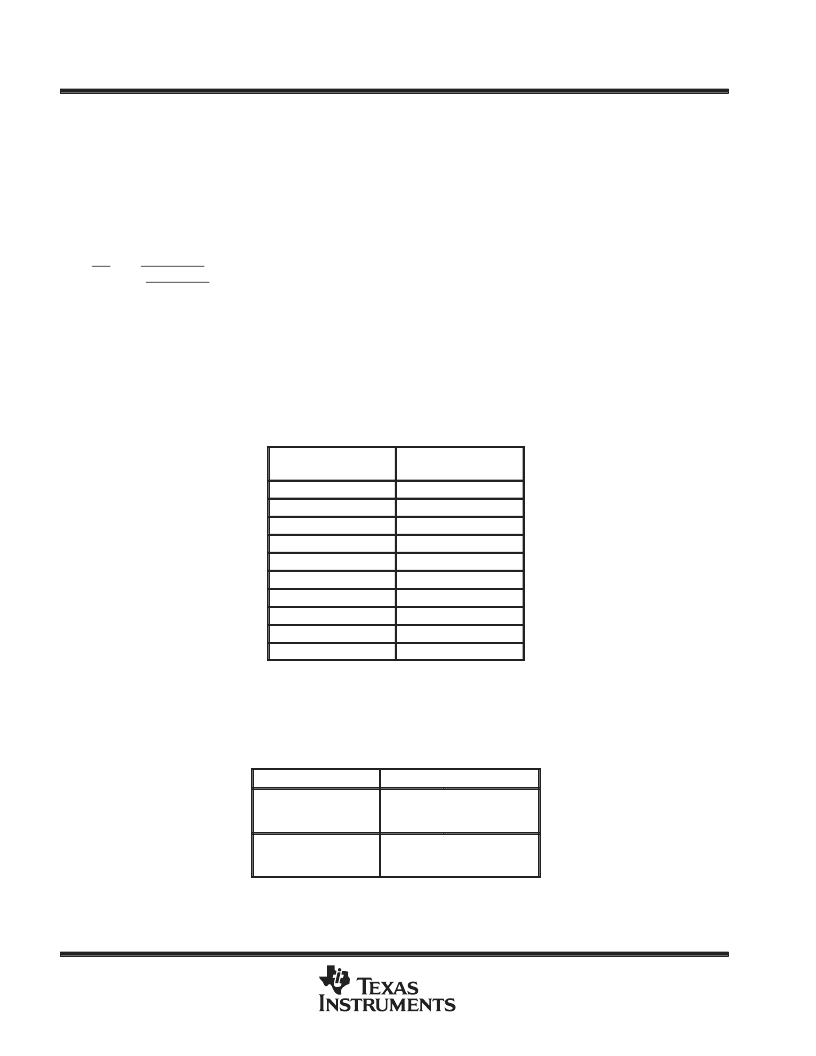
Table 5. Interrupt Priorities at the Level of the DSP Core
INTERRUPT
PRIORITY AT THE
DSP CORE
RESET
1
TI RESERVED
2
NMI
3
INT1
4
INT2
5
INT3
6
INT4
7
INT5
8
INT6
9
TI RESERVED
TI Reserved means that the address space is
reserved for Texas Instruments.
10
The inputs to these lines are controlled by the system module and the event manager as summarized in Table 6
and shown in Figure 5.
Table 6. Interrupt Lines Controlled by the System Module and Event Manager
PERIPHERAL
INTERRUPT LINES
System Module
INT1
INT5
INT6
NMI
Event Manager
INT2
INT3
INT4
相關(guān)PDF資料 |
PDF描述 |
|---|---|
| TMS320C240PQQ | 16-Bit Microcontroller |
| TMS320F240PQL | 16-Bit Microcontroller |
| TMS320F240PQQ | 16-Bit Microcontroller |
| TMS320F240PQS | 16-Bit Microcontroller |
| TMS320LC31-40 | Digital Signal Processor |
相關(guān)代理商/技術(shù)參數(shù) |
參數(shù)描述 |
|---|---|
| TMS320C240PQQ | 制造商:未知廠家 制造商全稱:未知廠家 功能描述:16-Bit Microcontroller |
| TMS320C241 | 制造商:未知廠家 制造商全稱:未知廠家 功能描述:16-Bit Digital Signal Processor |
| TMS320C241FNS | 制造商:未知廠家 制造商全稱:未知廠家 功能描述:16-Bit Digital Signal Processor |
| TMS320C241PGS | 制造商:未知廠家 制造商全稱:未知廠家 功能描述:16-Bit Digital Signal Processor |
| TMS320C242 | 制造商:TI 制造商全稱:Texas Instruments 功能描述:DSP CONTROLLER |
發(fā)布緊急采購,3分鐘左右您將得到回復(fù)。