- 您現(xiàn)在的位置:買賣IC網(wǎng) > PDF目錄98163 > TAS5504PAGG4 (TEXAS INSTRUMENTS INC) SPECIALTY CONSUMER CIRCUIT, PQFP64 PDF資料下載
參數(shù)資料
| 型號: | TAS5504PAGG4 |
| 廠商: | TEXAS INSTRUMENTS INC |
| 元件分類: | 消費家電 |
| 英文描述: | SPECIALTY CONSUMER CIRCUIT, PQFP64 |
| 封裝: | GREEN, PLASTIC, TQFP-64 |
| 文件頁數(shù): | 59/96頁 |
| 文件大?。?/td> | 1216K |
| 代理商: | TAS5504PAGG4 |
第1頁第2頁第3頁第4頁第5頁第6頁第7頁第8頁第9頁第10頁第11頁第12頁第13頁第14頁第15頁第16頁第17頁第18頁第19頁第20頁第21頁第22頁第23頁第24頁第25頁第26頁第27頁第28頁第29頁第30頁第31頁第32頁第33頁第34頁第35頁第36頁第37頁第38頁第39頁第40頁第41頁第42頁第43頁第44頁第45頁第46頁第47頁第48頁第49頁第50頁第51頁第52頁第53頁第54頁第55頁第56頁第57頁第58頁當(dāng)前第59頁第60頁第61頁第62頁第63頁第64頁第65頁第66頁第67頁第68頁第69頁第70頁第71頁第72頁第73頁第74頁第75頁第76頁第77頁第78頁第79頁第80頁第81頁第82頁第83頁第84頁第85頁第86頁第87頁第88頁第89頁第90頁第91頁第92頁第93頁第94頁第95頁第96頁
I2C Serial Control Interface (Slave Address 0x36)
55
SLES123 October 2004
TAS5504
When the correct number of bytes has been received, the TAS5504 starts processing the data.
The procedure to perform an incremental multi-byte write operation is as follows:
1. Start a normal I2C write operation by sending the device address, write bit, register subaddress, and the
first four bytes of the data to be written. At the end of that sequence, send a stop condition. At this point,
the register has been opened and accepts the remaining data that is sent by writing 4-byte blocks of data
to the append subaddress (0xFE).
2. At a later time, one or more append data transfers are performed to incrementally transfer the remaining
number of bytes in sequential order to complete the register write operation. Each of these append
operations will be composed of the device address, write bit, append subaddress (0xFE), and four bytes
of data followed by a stop condition.
3. The operation will be terminated due to an error condition and the data will be flushed:
a. If a new subaddress is written to the TAS5504 before the correct number of bytes have been written.
b. If more or less than 4 bytes are data written at the beginning or during any of the append operations.
c. If a read bit is sent.
4.6
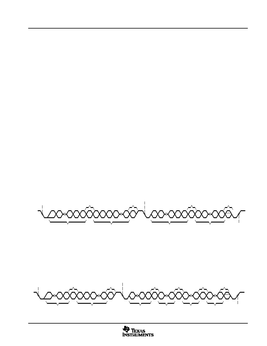
Single Byte Read
As shown in Figure 44, a single byte data read transfer begins with the master device transmitting a start
condition followed by the I2C device address and the read/write bit. For the data read transfer, both a write
followed by a read are actually done. Initially, a write is done to transfer the address byte or bytes of the internal
memory address to be read. As a result, the read/write bit will be a 0. After receiving the TAS5504 address
and the read/write bit, the TAS5504 responds with an acknowledge bit. In addition, after sending the internal
memory address byte or bytes, the master device transmits another start condition followed by the TAS5504
address and the read/write bit again. This time the read/write bit will be a 1, indicating a read transfer. After
receiving the TAS5504 and the read/write bit the TAS5504 again responds with an acknowledge bit. Next, the
TAS5504 transmits the data byte from the memory address being read. After receiving the data byte, the
master device transmits a not acknowledge followed by a stop condition to complete the single byte data read
transfer.
A6
A5
A0 R/W ACK A7
A6
A5
A4
A0 ACK
A6
A5
A0
ACK
Start
Condition
Stop
Condition
Acknowledge
I2C Device Address and
Read/Write Bit
Sub-Address
Data Byte
D7 D6
D1
D0 ACK
I2C Device Address and
Read/Write Bit
Not
Acknowledge
R/W
A1
Repeat Start
Condition
Figure 44. Single Byte Read Transfer
4.7
Multiple Byte Read
A multiple byte data read transfer is identical to a single byte data read transfer except that multiple data bytes
are transmitted by the TAS5504 to the master device as shown in Figure 45. Except for the last data byte,
the master device responds with an acknowledge bit after receiving each data byte.
A6
A0
ACK
Acknowledge
I2C Device Address and
Read/Write Bit
R/W
A6
A0 R/W ACK
A0 ACK
D7
D0 ACK
Start
Condition
Stop
Condition
Acknowledge
Last Data Byte
ACK
First Data Byte
Repeat Start
Condition
Not
Acknowledge
I2C Device Address and
Read/Write Bit
Sub-Address
Other Data Bytes
A7
A6
A5
D7
D0 ACK
Acknowledge
D7
D0
Figure 45. Multiple Byte Read Transfer
相關(guān)PDF資料 |
PDF描述 |
|---|---|
| TAS5508BPAGG4 | SPECIALTY CONSUMER CIRCUIT, PQFP64 |
| TAS5508BPAGRG4 | SPECIALTY CONSUMER CIRCUIT, PQFP64 |
| TAS5508BPAGR | SPECIALTY CONSUMER CIRCUIT, PQFP64 |
| TAS5508BPAG | SPECIALTY CONSUMER CIRCUIT, PQFP64 |
| TAS5508PAG | SPECIALTY CONSUMER CIRCUIT, PQFP64 |
相關(guān)代理商/技術(shù)參數(shù) |
參數(shù)描述 |
|---|---|
| TAS5504PAGR | 功能描述:音頻 DSP 4 Ch Digital Audio PWM Processor RoHS:否 制造商:Texas Instruments 工作電源電壓: 電源電流: 工作溫度范圍: 安裝風(fēng)格: 封裝 / 箱體: 封裝:Tube |
| TAS5504PAGRG4 | 功能描述:音頻 DSP 4 Ch Digital Audio PWM Processor RoHS:否 制造商:Texas Instruments 工作電源電壓: 電源電流: 工作溫度范圍: 安裝風(fēng)格: 封裝 / 箱體: 封裝:Tube |
| TAS5508 | 制造商:TI 制造商全稱:Texas Instruments 功能描述:8 Channel Digital Audio PWM Processor |
| TAS5508-5121K8EVM | 功能描述:音頻 IC 開發(fā)工具 TAS5508-TAS5121K8 Eval Mod RoHS:否 制造商:Texas Instruments 產(chǎn)品:Evaluation Kits 類型:Audio Amplifiers 工具用于評估:TAS5614L 工作電源電壓:12 V to 38 V |
| TAS5508-5122C6EVM | 功能描述:音頻 IC 開發(fā)工具 TAS5508-5122C6 Eval Mod RoHS:否 制造商:Texas Instruments 產(chǎn)品:Evaluation Kits 類型:Audio Amplifiers 工具用于評估:TAS5614L 工作電源電壓:12 V to 38 V |
發(fā)布緊急采購,3分鐘左右您將得到回復(fù)。