- 您現(xiàn)在的位置:買(mǎi)賣(mài)IC網(wǎng) > PDF目錄372122 > SC28L202A1 (NXP Semiconductors N.V.) Dual universal asynchronous receiver/transmitter DUART PDF資料下載
參數(shù)資料
| 型號(hào): | SC28L202A1 |
| 廠商: | NXP Semiconductors N.V. |
| 英文描述: | Dual universal asynchronous receiver/transmitter DUART |
| 中文描述: | 雙路通用異步接收器/發(fā)送器杜阿爾特 |
| 文件頁(yè)數(shù): | 21/77頁(yè) |
| 文件大小: | 531K |
| 代理商: | SC28L202A1 |
第1頁(yè)第2頁(yè)第3頁(yè)第4頁(yè)第5頁(yè)第6頁(yè)第7頁(yè)第8頁(yè)第9頁(yè)第10頁(yè)第11頁(yè)第12頁(yè)第13頁(yè)第14頁(yè)第15頁(yè)第16頁(yè)第17頁(yè)第18頁(yè)第19頁(yè)第20頁(yè)當(dāng)前第21頁(yè)第22頁(yè)第23頁(yè)第24頁(yè)第25頁(yè)第26頁(yè)第27頁(yè)第28頁(yè)第29頁(yè)第30頁(yè)第31頁(yè)第32頁(yè)第33頁(yè)第34頁(yè)第35頁(yè)第36頁(yè)第37頁(yè)第38頁(yè)第39頁(yè)第40頁(yè)第41頁(yè)第42頁(yè)第43頁(yè)第44頁(yè)第45頁(yè)第46頁(yè)第47頁(yè)第48頁(yè)第49頁(yè)第50頁(yè)第51頁(yè)第52頁(yè)第53頁(yè)第54頁(yè)第55頁(yè)第56頁(yè)第57頁(yè)第58頁(yè)第59頁(yè)第60頁(yè)第61頁(yè)第62頁(yè)第63頁(yè)第64頁(yè)第65頁(yè)第66頁(yè)第67頁(yè)第68頁(yè)第69頁(yè)第70頁(yè)第71頁(yè)第72頁(yè)第73頁(yè)第74頁(yè)第75頁(yè)第76頁(yè)第77頁(yè)

Philips Semiconductors
Objective specification
SC28L202
Dual UART
2000 Feb 10
15
Address Recognition and change of state interrupts become active
when the associated events occur and the arbitration value
generated thereby exceeds the threshold value programmed in the
ICR (Interrupt Control Register).
The transmitter and receiver functions have additional controls to
modify the condition upon which the initiation of interrupt ”bidding”
begins: the TxINT and RxINT fields of the MR0 and MR2 registers.
These fields can be used to start bidding or arbitration when the
RxFIFO is not empty, 50% full, 75% full or 100% full. For the
transmitter it is not full, 50% empty, 75% empty and empty.
Example: To increase the probability of transferring the contents of a
nearly full RxFIFO, do not allow it to start bidding until 50% or 75%
full. This will prevent its relatively high priority from winning the
arbitration process at low fill levels. A high threshold level could
accomplish the same thing, but may also mask out low priority
interrupt sources that must be serviced. Note that for fast channels
and/or long interrupt latency times using this feature should be used
with caution since it reduces the time the host CPU has to respond
to the interrupt request before receiver overrun occurs.
Setting interrupt priorities
The bid or interrupt number presented to the interrupt arbiter is
composed of character counts, channel codes, fixed and
programmable bit fields. The interrupt values are generated for
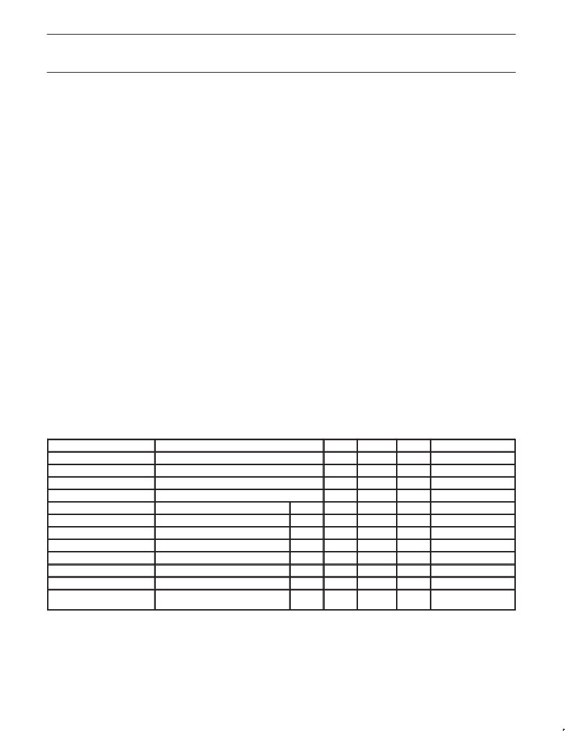
various interrupt sources as shown in Table 1. The value
represented by the bits 11 to 4 in Table 1 are compared against the
value represented by the “Threshold. The “Threshold”, bits 10 to 0 of
the ICR (Interrupt Control Register), is aligned such that bit 0 of the
threshold is compared to bit 1 of the interrupt value generated by
any of the sources. Whenever the value of the interrupt source is
greater than the threshold the interrupt will be generated.
The channel number arbitrates only against other channels. The
threshold is not used for the channel arbitration. This results in
channel B having the highest arbitration number. The decreasing
order is B to A. If all other parts of an arbitration cycle are equal then
the channel number will determine which channel will dominate in
the arbitration process.
Note several characteristics of Table 1 in bits 4:1. These bits contain
the identification of the bidding source as indicated below:
0000 No interrupt source active
x001 Receiver without error
x101 Receiver with error (errors are: parity, framing and
overrun. Break is not considered an error
x010 Transmitter
1110 Change of Break
0110 Change of State on I/O Ports
0111 Xon/Xoff Event
1011 Address Recognition
x100 Receiver watch dog
1000 Counter timer
1111 Rx Loop Back Error
The codes form bits 4:1 drive part of the interrupt vector modification
and the Global Interrupt Type Register. The codes are unique to
each source type and identify them completely. The channel
numbering progresses from ”A” to ”B” as the binary numbers 0 to 1
and identify the interrupting channel uniquely. As the channels
arbitrate ”B” will have the highest bidding value and ”A” the lowest
Table 1. Interrupt Values
Type
Bit 11:4
Bit 3
Bit 2
Bit 1
Bit 0
Receiver w/o error
RxFIFO filled Byte Count
0
0
1
Channel No.
Receiver w/ error
RxFIFO filled Byte Count
1
0
1
Channel No.
Receiver Watch–dog
RxFIFO filled Byte Count
1
0
0
Channel No.
Transmitter
TxFIFO empty Byte Count
0
1
0
Channel No.
Change of Break
Programmed Field
1
1
1
0
Channel No.
Rx Loop Back Error
Programmed Field
1
1
1
1
Channel No.
Change of State
Programmed Field
0
1
1
0
Port 0 or 1
Xon/Xoff
Programmed Field
0
1
1
1
Channel No.
Counter timer
Programmed Field
1
0
0
0
Counter 0 or 1
Address Recognition
Programmed Field
1
0
1
1
Channel No.
No interrupt
0
0
0
0
0
Threshold
Bits 7:0 of Interrupt Control Register
(ICR)
0
0
0
0
0
相關(guān)PDF資料 |
PDF描述 |
|---|---|
| SC28L202 | Dual universal asynchronous receiver/transmitter DUART |
| SC28L202A1B | Dual universal asynchronous receiver/transmitter DUART |
| SC28L202A1D | Dual universal asynchronous receiver/transmitter DUART |
| SC431CS8DE2 | Analog IC |
| SC431CS8DE3 | Analog IC |
相關(guān)代理商/技術(shù)參數(shù) |
參數(shù)描述 |
|---|---|
| SC28L202A1B | 制造商:PHILIPS 制造商全稱(chēng):NXP Semiconductors 功能描述:Dual universal asynchronous receiver/transmitter DUART |
| SC28L202A1D | 制造商:PHILIPS 制造商全稱(chēng):NXP Semiconductors 功能描述:Dual universal asynchronous receiver/transmitter DUART |
| SC28L202A1DGG | 功能描述:UART 接口集成電路 3-5V 2CH UART 3MBPS 256B FIFO RoHS:否 制造商:Texas Instruments 通道數(shù)量:2 數(shù)據(jù)速率:3 Mbps 電源電壓-最大:3.6 V 電源電壓-最小:2.7 V 電源電流:20 mA 最大工作溫度:+ 85 C 最小工作溫度:- 40 C 封裝 / 箱體:LQFP-48 封裝:Reel |
| SC28L202A1DGG,112 | 功能描述:UART 接口集成電路 3-5V 2CH UART 3MBPS RoHS:否 制造商:Texas Instruments 通道數(shù)量:2 數(shù)據(jù)速率:3 Mbps 電源電壓-最大:3.6 V 電源電壓-最小:2.7 V 電源電流:20 mA 最大工作溫度:+ 85 C 最小工作溫度:- 40 C 封裝 / 箱體:LQFP-48 封裝:Reel |
| SC28L202A1DGG,118 | 功能描述:UART 接口集成電路 3-5V 2CH UART 3MBPS RoHS:否 制造商:Texas Instruments 通道數(shù)量:2 數(shù)據(jù)速率:3 Mbps 電源電壓-最大:3.6 V 電源電壓-最小:2.7 V 電源電流:20 mA 最大工作溫度:+ 85 C 最小工作溫度:- 40 C 封裝 / 箱體:LQFP-48 封裝:Reel |
發(fā)布緊急采購(gòu),3分鐘左右您將得到回復(fù)。