- 您現(xiàn)在的位置:買賣IC網(wǎng) > PDF目錄372108 > SAA2501 (NXP Semiconductors N.V.) Digital Audio Broadcast DAB decoder PDF資料下載
參數(shù)資料
| 型號: | SAA2501 |
| 廠商: | NXP Semiconductors N.V. |
| 英文描述: | Digital Audio Broadcast DAB decoder |
| 中文描述: | 數(shù)字音頻廣播民建聯(lián)的解碼器 |
| 文件頁數(shù): | 39/52頁 |
| 文件大小: | 206K |
| 代理商: | SAA2501 |
第1頁第2頁第3頁第4頁第5頁第6頁第7頁第8頁第9頁第10頁第11頁第12頁第13頁第14頁第15頁第16頁第17頁第18頁第19頁第20頁第21頁第22頁第23頁第24頁第25頁第26頁第27頁第28頁第29頁第30頁第31頁第32頁第33頁第34頁第35頁第36頁第37頁第38頁當(dāng)前第39頁第40頁第41頁第42頁第43頁第44頁第45頁第46頁第47頁第48頁第49頁第50頁第51頁第52頁

January 1995
39
Philips Semiconductors
Preliminary specification
Digital Audio Broadcast (DAB) decoder
SAA2501
8.1.5.3
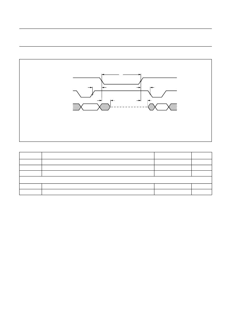
Halt mode
Table 39
Requirements for halt mode timing (see Fig.21)
SYMBOL
PARAMETER
REQUIREMENT
≥
190
≥
190
≥
190
UNIT
t
d1
t
L
t
h2
L3CLK HIGH to L3CLK LOW delay time after L3MODE HIGH
L3MODE LOW time
L3CLK hold time before L3MODE LOW
ns
ns
ns
Slave device to microcontroller
t
d2
t
d5
L3DATA enable time after L3MODE HIGH
L3DATA disable time after L3MODE LOW
0 < t
d2
≤
50
0 < t
d5
≤
50
ns
ns
Fig.21 Halt mode timing.
handbook, full pagewidth
MGB509
tL
L3CLK
L3MODE
d5
t
h2
t
td1
d2
t
L3DATA
IC to
microcontroller
8.2
SAA2501 L3 protocol enhancement options
The L3 interface on the SAA2501 is limited in speed,
dictated both by the maximum SAA2501 handling speed
and the upper frequencies of the L3 interfacing standard.
On the other hand, the SAA2501 offers several
enhancements to make a better use of the SAA2501 L3
interface capacity. The enhancements are optional. The
applicant chooses whether to use them or not.
8.2.1
T
ESTING
L3RDY
BY POLLING
L3DATA
The host must test status flag L3RDY to make sure
whether the SAA2501 L3 interface is ready to transfer data
item bytes. According to the general protocol, described in
Section 7.20.6, the status is read by first writing the
SAA2501 ‘read status’ operational address, after which
the status byte can be transferred. To avoid these status
byte transfers (thus reducing the host's load), after writing
the SAA2501 ‘read status’ operational address, L3RDY is
continuously copied to signal L3DATA during the period in
which no L3 transfers (i.e. status byte readings) are
performed. Meanwhile, L3MODE must be kept HIGH (no
L3 operational addresses may be written). As a result,
L3RDY can be tested as shown in Table 40.
相關(guān)PDF資料 |
PDF描述 |
|---|---|
| SAA2501H | Digital Audio Broadcast DAB decoder |
| SAA2502 | ISO/MPEG Audio Source Decoder |
| SAA2502H | ISO/MPEG Audio Source Decoder |
| SAA2503 | MPEG2 audio decoder(MPEG2 音頻譯碼器) |
| SAA2503HT | MPEG2 audio decoder |
相關(guān)代理商/技術(shù)參數(shù) |
參數(shù)描述 |
|---|---|
| SAA2501H | 制造商:PHILIPS 制造商全稱:NXP Semiconductors 功能描述:Digital Audio Broadcast DAB decoder |
| SAA2501HB-S | 制造商:未知廠家 制造商全稱:未知廠家 功能描述:Digital Audio Decoder & Support |
| SAA2502 | 制造商:PHILIPS 制造商全稱:NXP Semiconductors 功能描述:ISO/MPEG Audio Source Decoder |
| SAA2502H | 制造商:PHILIPS 制造商全稱:NXP Semiconductors 功能描述:ISO/MPEG Audio Source Decoder |
| SAA2503 | 制造商:PHILIPS 制造商全稱:NXP Semiconductors 功能描述:MPEG2 audio decoder |
發(fā)布緊急采購,3分鐘左右您將得到回復(fù)。