- 您現(xiàn)在的位置:買賣IC網(wǎng) > PDF目錄69032 > MEA224AG (CONEXANT SYSTEMS) 4 CHANNEL(S), 100M bps, LOCAL AREA NETWORK CONTROLLER, PBGA352 PDF資料下載
參數(shù)資料
| 型號: | MEA224AG |
| 廠商: | CONEXANT SYSTEMS |
| 元件分類: | 微控制器/微處理器 |
| 英文描述: | 4 CHANNEL(S), 100M bps, LOCAL AREA NETWORK CONTROLLER, PBGA352 |
| 封裝: | 35 X 35 MM, 2.33 MM HEIGHT, PLASTIC, MS-034, BGA-352 |
| 文件頁數(shù): | 3/29頁 |
| 文件大?。?/td> | 519K |
| 代理商: | MEA224AG |
第1頁第2頁當前第3頁第4頁第5頁第6頁第7頁第8頁第9頁第10頁第11頁第12頁第13頁第14頁第15頁第16頁第17頁第18頁第19頁第20頁第21頁第22頁第23頁第24頁第25頁第26頁第27頁第28頁第29頁
PRELI
MI
NARY
D
A
TA
S
H
EET
XpressFlow-2001 Series –
EA-224
Ethernet Switch Chip-set
4-Port 10/100M Ethernet Access Controller
1997 Zarlink Semiconductor Inc.
Page: 10
Rev. 4.0 –December, 1997
4.2 Management Bus Interface
Supports various industry standard micro-
processors including:
Intel 186, 386, and 486 family or equivalent
Motorola MPC series embedded processors
Easily adapts to other industry standard CPUs
Provides separate Address and Data bus
Supports Big & Little Endian byte ordering
Supports 16-bit Data Bus
Supports early RDY cycle
Meets timing requirement for Intel/AMD
186 family processors
Supports 1X or 2X CPU Clock
2X CPU Clock for 386 family processors
Provides a single interrupt signal to Switch
Manager CPU
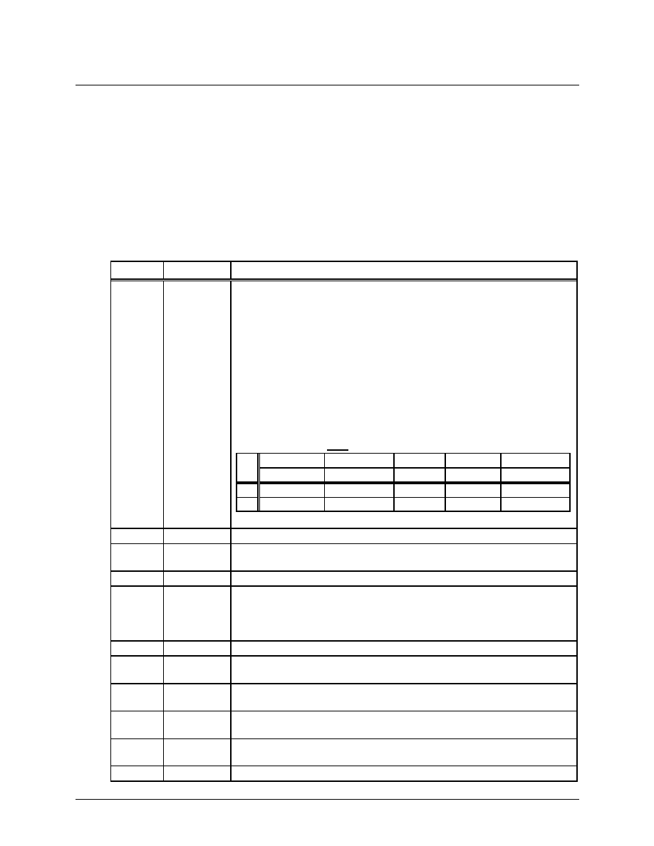
4.2.1 Pin Description
Symbol
Type
Name & Functions
P_C[4:0]
CMOS Input Processor Configuration bit [4:0]: – During the Reset Cycle, the
P_C[4:0] pins provides the processor configuration. By using external
weak pull-up or -down resistors, they define the External Management
Bus Interface Configuration. These inputs are sampled at the trailing
edge of the Reset cycle.
C[0] – Defines the CPU Clock input is 1X or 2X clock
C[1] – Selects either Big or Little Endian byte ordering
C[2] – Defines the polarity of the P_RWC (Rd/Wr Control) input
C[3] – Defines the CPU Bus width – For EA-208, it is default to 16-bit CPU
Bus interface, and the setting of this bit is ignored.
C[4] – Defines the timing relationship between P_RDY and P_D[15:0] valid.
If C[4] is High, the P_D[15:0] are valid along in the same clock period
as P_RDY is asserted. If C[4] is Low, the P_RDY is asserted one
clock period early ahead of the P_D[15:0] are valid.
C[0]
C[1]
C[2]
C[3]
C[4]
CPU Clock
Byte Order
RWC
Bus Size
RDY Timing
Lo
1X Clock
Little Endian
P_R/W#
n/a
Normal
Hi
2x Clock
Big Endian
P_W/R#
n/a
Early
After RESET, these pins are used as XpressFlow Bus Data bit [31:27].
P_A[11:1] TTL In (5VT) Address Bus Bit [11:1] – I/O port address
P_D[15:0] TTL I/O-TS
(5VT)
Data Bus Bit [15:0] – a 16-bit synchronous data bus.
P_ADS#
TTL In (5VT) Address Strobe – indicates valid address is on the bus
P_RWC
TTL Input
(5VT)
Read/Write Control – indicates the current bus cycle is a read or write
cycle. C[1] defines the polarity of this signal during the Reset cycle.
C[1]=0
P_R/W# is used for PowerPC or other similar processors.
C[1]=1
P_W/R# is used for 386, 486 or other similar processors
P_RDY#
TTL Out-OD Data Ready – timing indicates for bus data valid
P_BS16# TTL Out-OD Bus Size 16 – response to bus master that the EA208 only supports 16-
bit data bus width.
P_CS#
TTL Input
(5VT)
Chip Select – indicates the XpressFlow Engine is the target for the cur-
rent bus operation.
P_INT
? CMOS Out-
put
Interrupt Request to Switch Manager CPU The polarity of this signal
output is programmable via chip configuration register.
P_RST#
TTL In-ST
(5VT)
CPU Reset – Synchronous reset Input from Switch Manager CPU
P_CLK
TTL In (5VT) CPU Clock – 2X Clock for 386 family, and 1X Clock for the others
相關(guān)PDF資料 |
PDF描述 |
|---|---|
| MEGA32C1-ESAZ | 8-BIT, FLASH, 16 MHz, RISC MICROCONTROLLER, PQFP32 |
| MEGA32C1-ESMZ | 8-BIT, FLASH, 16 MHz, RISC MICROCONTROLLER, QCC32 |
| MFR4300MAE40 | 2 CHANNEL(S), 10M bps, SERIAL COMM CONTROLLER, PQFP64 |
| MG80C18612883B | 16-BIT, 12.5 MHz, MICROPROCESSOR, CPGA68 |
| MG80C186-10 | 16-BIT, 10 MHz, MICROPROCESSOR, CPGA68 |
相關(guān)代理商/技術(shù)參數(shù) |
參數(shù)描述 |
|---|---|
| MEA250-12DA | 功能描述:分立半導(dǎo)體模塊 500 Amps 1200V RoHS:否 制造商:Infineon Technologies 產(chǎn)品:Thyristor Power Modules 類型:Phase Controls 安裝風格:Screw 封裝 / 箱體:DT61 封裝: |
| MEA300-06DA | 功能描述:分立半導(dǎo)體模塊 600 Amps 600V RoHS:否 制造商:Infineon Technologies 產(chǎn)品:Thyristor Power Modules 類型:Phase Controls 安裝風格:Screw 封裝 / 箱體:DT61 封裝: |
| MEA30168303 | 制造商:LG Corporation 功能描述:Guide |
| MEA30168304 | 制造商:LG Corporation 功能描述:Guide |
| MEA30239904 | 制造商:LG Corporation 功能描述:Guide |
發(fā)布緊急采購,3分鐘左右您將得到回復(fù)。