- 您現(xiàn)在的位置:買賣IC網(wǎng) > PDF目錄370960 > M38C13E6HP (Mitsubishi Electric Corporation) SINGLE-CHIP 8-BIT CMOS MICROCOMPUTER PDF資料下載
參數(shù)資料
| 型號: | M38C13E6HP |
| 廠商: | Mitsubishi Electric Corporation |
| 英文描述: | SINGLE-CHIP 8-BIT CMOS MICROCOMPUTER |
| 中文描述: | 單芯片8位CMOS微機 |
| 文件頁數(shù): | 39/59頁 |
| 文件大?。?/td> | 1063K |
| 代理商: | M38C13E6HP |
第1頁第2頁第3頁第4頁第5頁第6頁第7頁第8頁第9頁第10頁第11頁第12頁第13頁第14頁第15頁第16頁第17頁第18頁第19頁第20頁第21頁第22頁第23頁第24頁第25頁第26頁第27頁第28頁第29頁第30頁第31頁第32頁第33頁第34頁第35頁第36頁第37頁第38頁當(dāng)前第39頁第40頁第41頁第42頁第43頁第44頁第45頁第46頁第47頁第48頁第49頁第50頁第51頁第52頁第53頁第54頁第55頁第56頁第57頁第58頁第59頁

SINGLE-CHIP 8-BIT CMOS MICROCOMPUTER
MITSUBISHI MICROCOMPUTERS
38C1 Group
39
CLOCK GENERATING CIRCUIT
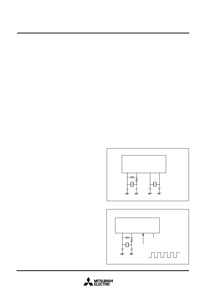
The oscillation circuit of 38C1 group can be formed by connecting
an oscillator, capacitor and resistor between X
IN
and X
OUT
(X
CIN
and X
COUT
). To supply a clock signal externally, input it to the X
IN
pin and make the X
OUT
pin open. The clocks that are externally
generated cannot be directly input to X
CIN
. Use the circuit con-
stants in accordance with the oscillator manufacturer's recom-
mended values. No external resistor is needed between X
IN
and
X
OUT
since a feed-back resistor exists on-chip. However, a 10 M
external feed-back resistor is needed between X
CIN
and X
COUT
.
Immediately after reset is released, only the built-in ring oscillator
starts oscillating, X
IN
-X
OUT
oscillation stops oscillating, and X
CIN
and X
COUT
pins function as I/O ports.
Operation mode
(1) Ring oscillator mode
The internal clock
φ
is the built-in ring oscillator oscillation divided
by 8.
(2) Middle-speed mode
The internal clock
φ
is the frequency of X
IN
divided by 8.
(3)High-speed mode
The internal clock
φ
is half the frequency of X
IN
.
(4) Low-speed mode
The internal clock
φ
is half the frequency of X
CIN
.
After reset release and when system returns from the stop mode,
the ring oscillator mode is selected.
Refer to the clock state transition diagram for the setting of transi-
tion to each mode.
The X
IN
–
X
OUT
oscillation is controlled by the bit 5 of CPUM, and
the sub-clock oscillation is controlled by the bit 4 of CPUM. When
the mode is switched to the ring oscillator mode, set the bit 3 of
CPUM to
“
1
”
.
In the ring oscillator mode, the oscillation by the oscillator can be
stopped. In the low-speed mode, the power consumption can be
reduced by stopping the X
IN
–
X
OUT
oscillation.
When the mode is switched from the ring oscillator mode to the
low-speed mode, the built-in ring oscillator is stopped.
Set enough time for oscillation to stabilize by programming to re-
start the stopped oscillation and switch the operation mode. Also,
set enough time for oscillation to stabilize by programming to
switch the timer count source .
Note:
If you switch the mode between ring oscillator mode,
middle/high-speed mode and low-speed mode, stabilize
both X
IN
and X
CIN
oscillations. Especially be careful imme-
diately after power-on and at returning from stop mode. Re-
fer to the clock state transition diagram for the setting of
transition to each mode. Set the frequency in the condition
that f(X
IN
) > 3
f(X
CIN
).
When the middle- and high-speed mode are not used (X
IN
-
X
OUT
oscillation and external clock input are not
performed), connect X
IN
to V
CC
through a resistor.
Fig. 40 Oscillator circuit
Fig. 41 External clock input circuit
Oscillation Control
(1) Stop mode
Set the timer 1 interrupt enable bit to disabled (
“
0
”
) before execut-
ing the STP instruction. If the STP instruction is executed, the in-
ternal clock
φ
stops at an
“
H
”
level, and main clock, ring oscillator
and sub-clock oscillators stop.
In this time,
“
01
16
”
is set to timer 1 and the ring oscillator is con-
nected forcibly for the system clock and the timer 1 count source.
Also, the bits of the timer 123 mode register except bit 4 are
cleared to
“
0
”
.
When an external interrupt is received, the clock oscillated before
stop mode and the ring oscillator start oscillating.
However, bit 3 of CPUM is set to
“
1
”
forcibly and system returns to
the ring oscillator mode.
Tthe internal clock
φ
is supplied to the CPU after timer 1
underflows. However, when the system clock is switched from the
ring oscillator to main clock and sub-clock, generate the wait time
enough for oscillation stabilizing by program.
(2) Wait mode
If the WIT instruction is executed, only the internal clock
φ
stops at
an
“
H
”
level. The states of main clock, ring oscillator and sub-clock
are the same as the state before the executing the WIT instruction
and the oscillation does not stop. Since the internal clock
φ
re-
starts when an interrupt is received, the instruction is executed im-
mediately.
X
C
I
N
C
IN
C
OUT
C
C
I
N
C
COUT
R
f
R
d
X
O
U
T
X
I
N
X
C
O
U
T
E
O
x
t
T
e
r
n
a
l
o
s
c
i
l
l
a
t
i
o
n
c
i
r
c
u
i
t
O
p
e
n
V
C
C
V
S
S
C
C
I
N
R
f
R
d
C
C
U
X
C
I
N
X
OUT
X
I
N
X
C
O
U
T
相關(guān)PDF資料 |
PDF描述 |
|---|---|
| M38C24M6-051HP | SINGLE-CHIP 8-BIT CMOS MICROCOMPUTER |
| M38C24M4-XXXFP | SINGLE-CHIP 8-BIT CMOS MICROCOMPUTER |
| M38C24M4-XXXHP | SINGLE-CHIP 8-BIT CMOS MICROCOMPUTER |
| M38C24M6-XXXFP | SINGLE-CHIP 8-BIT CMOS MICROCOMPUTER |
| M38C24M6-XXXHP | SINGLE-CHIP 8-BIT CMOS MICROCOMPUTER |
相關(guān)代理商/技術(shù)參數(shù) |
參數(shù)描述 |
|---|---|
| M38C13RLFS | 制造商:Renesas Electronics Corporation 功能描述:EMULATION MCU/8BIT CMOS EMULATION CHIP - Bulk |
| M38C24M4-XXXFP | 制造商:MITSUBISHI 制造商全稱:Mitsubishi Electric Semiconductor 功能描述:SINGLE-CHIP 8-BIT CMOS MICROCOMPUTER |
| M38C24M4-XXXHP | 制造商:MITSUBISHI 制造商全稱:Mitsubishi Electric Semiconductor 功能描述:SINGLE-CHIP 8-BIT CMOS MICROCOMPUTER |
| M38C24M6-051HP | 制造商:MITSUBISHI 制造商全稱:Mitsubishi Electric Semiconductor 功能描述:SINGLE-CHIP 8-BIT CMOS MICROCOMPUTER |
| M38C24M6-XXXFP | 制造商:MITSUBISHI 制造商全稱:Mitsubishi Electric Semiconductor 功能描述:SINGLE-CHIP 8-BIT CMOS MICROCOMPUTER |
發(fā)布緊急采購,3分鐘左右您將得到回復(fù)。