- 您現(xiàn)在的位置:買賣IC網(wǎng) > PDF目錄67763 > M37643M8-XXXHP 8-BIT, MROM, 12 MHz, MICROCONTROLLER, PQFP80 PDF資料下載
參數(shù)資料
| 型號: | M37643M8-XXXHP |
| 元件分類: | 微控制器/微處理器 |
| 英文描述: | 8-BIT, MROM, 12 MHz, MICROCONTROLLER, PQFP80 |
| 封裝: | 12 X 12 MM, 0.50 MM PITCH, PLASTIC, LQFP-80 |
| 文件頁數(shù): | 20/120頁 |
| 文件大小: | 1253K |
| 代理商: | M37643M8-XXXHP |
第1頁第2頁第3頁第4頁第5頁第6頁第7頁第8頁第9頁第10頁第11頁第12頁第13頁第14頁第15頁第16頁第17頁第18頁第19頁當(dāng)前第20頁第21頁第22頁第23頁第24頁第25頁第26頁第27頁第28頁第29頁第30頁第31頁第32頁第33頁第34頁第35頁第36頁第37頁第38頁第39頁第40頁第41頁第42頁第43頁第44頁第45頁第46頁第47頁第48頁第49頁第50頁第51頁第52頁第53頁第54頁第55頁第56頁第57頁第58頁第59頁第60頁第61頁第62頁第63頁第64頁第65頁第66頁第67頁第68頁第69頁第70頁第71頁第72頁第73頁第74頁第75頁第76頁第77頁第78頁第79頁第80頁第81頁第82頁第83頁第84頁第85頁第86頁第87頁第88頁第89頁第90頁第91頁第92頁第93頁第94頁第95頁第96頁第97頁第98頁第99頁第100頁第101頁第102頁第103頁第104頁第105頁第106頁第107頁第108頁第109頁第110頁第111頁第112頁第113頁第114頁第115頁第116頁第117頁第118頁第119頁第120頁
116
7643 Group
SINGLE-CHIP 8-BIT CMOS MICROCOMPUTER
MITSUBISHI MICROCOMPUTERS
PRELIMINAR
Y
Notice:
This
is not
a final
specification.
Some
parametric
limits
are
subject
to
change.
USAGE NOTES
Oscillator Connection Notice
The built-in feedback register (400
) is internally connected be-
tween pins XIN and XOUT.
Power Supply Pins Treatment Notice
Please connect 0.1
F and 4.7 F capacitors in parallel between
pins Vcc and Vss, and pins AVss and AVcc.
These capacitors must be connected as close as possible be-
tween the DC supply and GND pins, and also the analog supply
pin and corresponding GND pin.
Wiring patterns for these supply and GND pins must be wider than
other signal patterns.
These filter capacitors should not be placed near the LPF pins as
they will cause noise problems
Rest
Pin
Treatment
Notice
(Noise
Elimination)
If the reset input signal rises very slowly, we recommend attaching
a capacitor, such as a 1000 pF ceramic capacitor with excellent
high frequency characteristics, between the RESET pin and the
Vss pin.
Please note the following two issues for this capacitor connection.
(1) Capacitor wiring pattern must be as short as possible (within
20 mm).
(2) The user must perform an application level operation test.
LPF Pin Treatment Notice
All passive components must be located as close as possible to
the LPF pin.
0.1
F
680 pF
LPF pin
AVSS pin
1 k
Fig. 101 Passive components near LPF pin
USB
Transceiver
Treatment
(Noise
Elimination)
The Full-Speed USB2.0 specification requires a driver -imped-
ance 28 to 44
. (Refer to Clause 7.1.1.1 Full-speed (12 Mb/s)
Driver Characteristics in the USB specification.) In order to meet
the USB specification impedance requirements, connect a resis-
tor (27
to 33 recommended) in series to the USB D+ pin and
the USB D- pin.
In addition, in order to reduce the ringing and control the falling/
rising timing of USB D+/D- and a crossover point, connect a ca-
pacitor between the USB D+/D- pins and the Vss pin if necessary.
The values and structure of those peripheral elements depend on
the impedance characteristics and the layout of the printed circuit
board. Accordingly, evaluate your system and observe waveforms
before actual use and decide use of elements and the values of
resistors and capacitors.
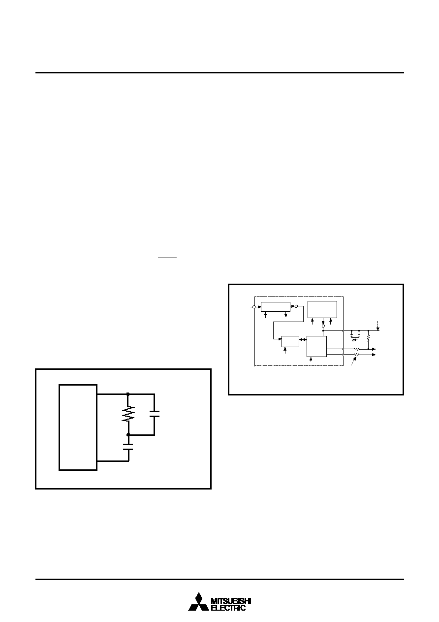
Connect a capacitor between the Ext. Cap. pin and the Vss pin.
The capacitor should have a 2.2
F capacitor (Tantalum capaci-
tor) and a 0.1
F capacitor (ceramic capacitor) connected in
parallel. Figure 102 for the proper positions of the peripheral
components.
XIN
enable
lock
FSE
LS
USBC5
enable
USB Clock
(48 MHz)
USB FCU
enable
USBC7
USB
transceiver
enable
USBC7
DC-DC converter
enable
USBC4
current
mode
USBC3
Ext. Cap.
2
.2
F
0
.1
F
D+
D-
1
.5
k
Frequency Synthesizer
Note 1
Notes 1: In Vcc = 3.3 V, connect to Vcc. In Vcc =5 V, do not connect the external DC-DC
converter to the Ext. Cap pin.
2: The resistors values depend on the layout of the printed circuit board.
Note 2
Fig.102 Peripheral circuit
In Vcc = 3.3 V operation, connect the Ext. Cap. pin directly to the
Vcc pin in order to supply power to the USB transceiver. In addi-
tion, you will need to disable the DC-DC converter in this
operation (set bit 4 of the USB control register to “0”.) If you are
using the bus powered supply in Vcc = 3.3 V operation, the DC-
DC converter must be placed outside the MCU.
In Vcc = 5 V operation, do not connect the external DC-DC con-
verter to the Ext. Cap. pin. Use the built-in DC-DC converter by
enabling the USB line driver.
Make sure the USB D+/D- lines do not cross any other wires.
Keep a large GND area to protect the USB lines. Also, make sure
you use a USB specification compliant connecter for the connec-
tion.
AVss and AVcc Pin Treatment Notice (Noise
Elimination)
An insulation connector (Ferrite Beads) must be connected be-
tween AVss and Vss pins and between AVcc and Vcc pins.
相關(guān)PDF資料 |
PDF描述 |
|---|---|
| M37702S1LGP | 16-BIT, 8 MHz, MICROCONTROLLER, PQFP80 |
| M37702M2LXXXGP | 16-BIT, MROM, 8 MHz, MICROCONTROLLER, PQFP80 |
| M37702M2LXXXHP | 16-BIT, MROM, 8 MHz, MICROCONTROLLER, PQFP80 |
| M37703MDBSP | 16-BIT, MROM, 25 MHz, MICROCONTROLLER, PDIP64 |
| M37721S1BFP | 16-BIT, 25 MHz, MICROCONTROLLER, PQFP100 |
相關(guān)代理商/技術(shù)參數(shù) |
參數(shù)描述 |
|---|---|
| M3764A-12 | 制造商:OK International 功能描述: |
| M3765 | 制造商:未知廠家 制造商全稱:未知廠家 功能描述:HORN/SIREN WITH SOFT CHIRP 6 ALARM SOUNDS |
| M3766 | 制造商:未知廠家 制造商全稱:未知廠家 功能描述:HORN/SIREN WITH SOFT CHIRP 6 ALARM SOUNDS |
| M37702E2LGP | 制造商:Mitsubishi Electric 功能描述: |
| M37702E4BFS | 制造商:Renesas Electronics Corporation 功能描述:EPROM MCU/8BIT CMOS EMULATION CHIP - Bulk |
發(fā)布緊急采購,3分鐘左右您將得到回復(fù)。