- 您現(xiàn)在的位置:買賣IC網(wǎng) > PDF目錄69009 > M30222FGFP 16-BIT, FLASH, MICROCONTROLLER, PQFP100 PDF資料下載
參數(shù)資料
| 型號: | M30222FGFP |
| 元件分類: | 微控制器/微處理器 |
| 英文描述: | 16-BIT, FLASH, MICROCONTROLLER, PQFP100 |
| 封裝: | PLASTIC, QFP-100 |
| 文件頁數(shù): | 73/236頁 |
| 文件大小: | 1955K |
| 代理商: | M30222FGFP |
第1頁第2頁第3頁第4頁第5頁第6頁第7頁第8頁第9頁第10頁第11頁第12頁第13頁第14頁第15頁第16頁第17頁第18頁第19頁第20頁第21頁第22頁第23頁第24頁第25頁第26頁第27頁第28頁第29頁第30頁第31頁第32頁第33頁第34頁第35頁第36頁第37頁第38頁第39頁第40頁第41頁第42頁第43頁第44頁第45頁第46頁第47頁第48頁第49頁第50頁第51頁第52頁第53頁第54頁第55頁第56頁第57頁第58頁第59頁第60頁第61頁第62頁第63頁第64頁第65頁第66頁第67頁第68頁第69頁第70頁第71頁第72頁當(dāng)前第73頁第74頁第75頁第76頁第77頁第78頁第79頁第80頁第81頁第82頁第83頁第84頁第85頁第86頁第87頁第88頁第89頁第90頁第91頁第92頁第93頁第94頁第95頁第96頁第97頁第98頁第99頁第100頁第101頁第102頁第103頁第104頁第105頁第106頁第107頁第108頁第109頁第110頁第111頁第112頁第113頁第114頁第115頁第116頁第117頁第118頁第119頁第120頁第121頁第122頁第123頁第124頁第125頁第126頁第127頁第128頁第129頁第130頁第131頁第132頁第133頁第134頁第135頁第136頁第137頁第138頁第139頁第140頁第141頁第142頁第143頁第144頁第145頁第146頁第147頁第148頁第149頁第150頁第151頁第152頁第153頁第154頁第155頁第156頁第157頁第158頁第159頁第160頁第161頁第162頁第163頁第164頁第165頁第166頁第167頁第168頁第169頁第170頁第171頁第172頁第173頁第174頁第175頁第176頁第177頁第178頁第179頁第180頁第181頁第182頁第183頁第184頁第185頁第186頁第187頁第188頁第189頁第190頁第191頁第192頁第193頁第194頁第195頁第196頁第197頁第198頁第199頁第200頁第201頁第202頁第203頁第204頁第205頁第206頁第207頁第208頁第209頁第210頁第211頁第212頁第213頁第214頁第215頁第216頁第217頁第218頁第219頁第220頁第221頁第222頁第223頁第224頁第225頁第226頁第227頁第228頁第229頁第230頁第231頁第232頁第233頁第234頁第235頁第236頁
1-165
Under
development
Specifications in this manual are tentative and subject to change
Rev. H
A-D Converter
MITSUBISHI MICROCOMPUTERS
M30222 Group
SINGLE-CHIP 16-BIT CMOS MICROCOMPUTER
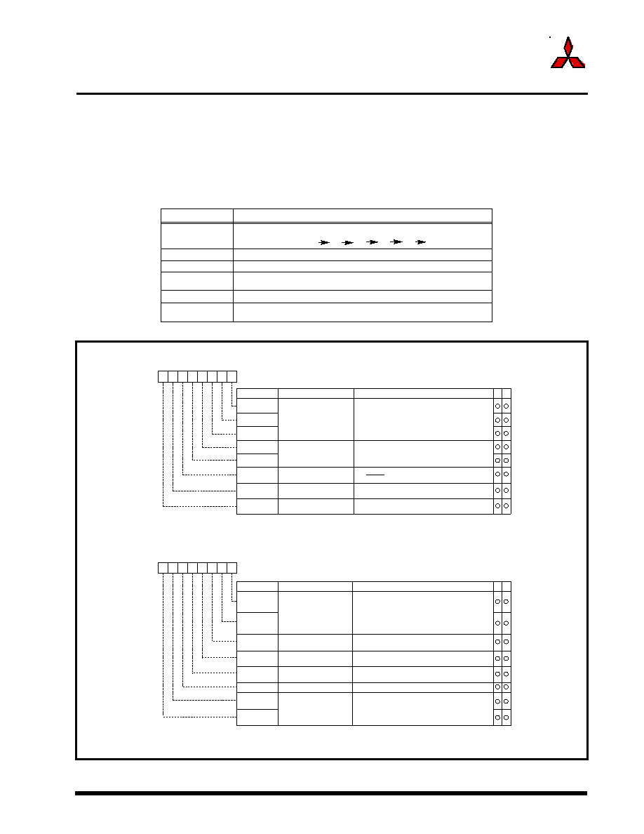
(5) Repeat sweep mode 1
In repeat sweep mode 1, all pins are used for A-D conversion with emphasis on the pin or pins
selected using the A-D sweep pin select bit. Table 1.54 shows the specifications of repeat sweep
mode 1. Figure 1.133 shows the A-D control register in repeat sweep mode 1.
Table 1.54. Repeat sweep mode 1 specifications
Fig. 1.133. A-D conversion register in repeat sweep mode 1
Item
Specification
Function
All pins perform repeat sweep A-D conversion, with emphasis on the pin or pins selected
by the A-D sweep pin select bit.
Example: AN0 selected AN0
AN1
AN0
AN2
AN0
AN3, etc.
Start condition
Writing 1 to A-D conversion start flag
Stop condition
Writing 0 to A-D conversion start flag
Interrupt request
generation timing
None generated
Input pin
AN0 (1 pin), AN0 and AN1 (2 pins), AN0 and AN2 (3 pins), AN0 and AN3(4 pins)
Reading A-D
converter results
Read A-D register corresponding to selected pin (at any time)
A-D control register 0 (Note)
Symbol
Address
When reset
ADCON0
03D616
00000XXX2
b7
b6
b5
b4
b3
b2
b1
b0
Analog input pin
select bit
CH0
Bit symbol
Bit name
Function
CH1
CH2
A-D operation mode
select bit 0
1 1 : Repeat sweep mode 1
MD0
MD1
Trigger select bit
0 : Software trigger
1 : AD TRG trigger
TRG
ADST
A-D conversion start flag
0 : A-D conversion disabled
1 : A-D conversion started
Frequency select bit 0
0 : fAD/4 is selected
1 : fAD/2 is selected
CKS0
W
R
A-D control register 1 (Note 1)
Symbol
Address
When reset
ADCON1
03D716
0016
Bit name
Function
Bit symbol
b7
b6
b5
b4
b3
b2
b1
b0
A-D sweep pin select bit
SCAN0
SCAN1
MD2
BITS
8/10-bit mode select bit
0 : 8-bit mode
1 : 10-bit mode
VCUT
OPA0
Vref connect bit
1 : Repeat sweep mode 1
OPA1
A-D operation mode
select bit 1
1 : Vref connected
External op-amp
connection mode
bit (Note 2)
W
R
1 1
Invalid in repeat sweep mode 1
1
Note 1: If the A-D control register is rewritten during A-D conversion, the conversion result
is indeterminate.
Note 2: Neither ‘01’ nor ‘10’ can be selected with the external op-amp connection mode bit.
b4 b3
When repeat sweep mode 1 is selected
0 0 : AN 0 (1 pin)
0 1 : AN 0, AN1 (2 pins)
1 0 : AN 0 to AN2 (3 pins)
1 1 : AN 0 to AN3 (4 pins)
b1 b0
0 0 : ANEX0 and ANEX1 are not used
0 1 : ANEX0 input is A-D converted
1 0 : ANEX1 input is A-D converted
1 1 : External op-amp connection mode
b7 b6
1
Note: If the A-D control register is rewritten during A-D conversion, the conversion result
is indeterminate.
Frequency select bit 1
0 : fAD/2 or fAD/4 is selected
1 : fADis selected
CKS1
相關(guān)PDF資料 |
PDF描述 |
|---|---|
| M30240M6-XXXFP | 16-BIT, MROM, 12 MHz, MICROCONTROLLER, PQFP80 |
| M30240M6-XXXFP | 16-BIT, MROM, 12 MHz, MICROCONTROLLER, PQFP80 |
| M30240M5-XXXFP | 16-BIT, MROM, 12 MHz, MICROCONTROLLER, PQFP80 |
| M30240M6-XXXXFP | 16-BIT, MROM, 12 MHz, MICROCONTROLLER, PQFP80 |
| M30240ECFP | 16-BIT, OTPROM, 12 MHz, MICROCONTROLLER, PQFP80 |
相關(guān)代理商/技術(shù)參數(shù) |
參數(shù)描述 |
|---|---|
| M30222FGGP | 制造商:MITSUBISHI 制造商全稱:Mitsubishi Electric Semiconductor 功能描述:SINGLE-CHIP 16-BIT CMOS MICROCOMPUTER |
| M30222FG-XXXFP | 制造商:MITSUBISHI 制造商全稱:Mitsubishi Electric Semiconductor 功能描述:SINGLE-CHIP 16-BIT CMOS MICROCOMPUTER |
| M30222FG-XXXGP | 制造商:MITSUBISHI 制造商全稱:Mitsubishi Electric Semiconductor 功能描述:SINGLE-CHIP 16-BIT CMOS MICROCOMPUTER |
| M3024 | 功能描述:速度傳感器 ELECTRO RoHS:否 制造商:Honeywell 最大工作溫度:+ 120 C 電源電壓: 電源電流: 輸出電壓:190 V 工作電源電壓: 安裝風(fēng)格:Screw 最小工作溫度:- 55 C 系列:High Output VRS |
| M30240 | 制造商:MITSUBISHI 制造商全稱:Mitsubishi Electric Semiconductor 功能描述:M30240 Group Specification |
發(fā)布緊急采購,3分鐘左右您將得到回復(fù)。