- 您現(xiàn)在的位置:買賣IC網(wǎng) > PDF目錄378652 > LS7266R1 (LSI Corporation) 24-BIT DUAL-AXIS QUADRATURE COUNTER PDF資料下載
參數(shù)資料
| 型號: | LS7266R1 |
| 廠商: | LSI Corporation |
| 元件分類: | 通用總線功能 |
| 英文描述: | 24-BIT DUAL-AXIS QUADRATURE COUNTER |
| 中文描述: | 24位雙軸正交計數(shù)器 |
| 文件頁數(shù): | 4/14頁 |
| 文件大小: | 71K |
| 代理商: | LS7266R1 |
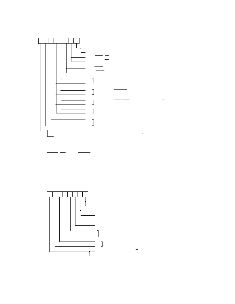
Input/Output Control Register: XIOR and YIOR
The functional modes of the programmable input and output pins are written into the IORs.
7
6
5
4
3
2
1
0
0 : Disable inputs A and B
1 : Enable inputs A and B
0 : LCNTR/LOL pin is Load CNTR input
1 : LCNTR/LOL pin is Load OL input
0 : RCNTR/ABG pin is Reset CNTR input
1 : RCNTR/ABG pin is A and B Enable gate
0
0
IOR
0
: FLG1 pin is COMPARE output; FLG2 pin is BORROW output
1
: FLG1 pin is CARRY output; FLG2 pin is BORROW output
: FLG1 pin is Carry/Borrow output and FLG2 pin is U/D (FLAG register bit 5)
: FLG1 is IDX (FLAG register bit 6); FLG2 is E (FLAG register bit 4)
0: Select IOR addressed by X/Y input
1: Select both XIOR and YIOR together (Note: D7=1 overrides X/Y input)
: Select IOR
1
1
1
1
0
0
7266R1-120899-4
INDEX CONTROL REGISTERS: XIDR and YIDR
Either the LCNTR/LOL or the RCNTR/ABG inputs can be initialized to operate as an index input. When
initialized as such, the index signal from the encoder, applied to one of these inputs performs either the
Reset CNTR or the Load CNTR or the Load OL operation synchronously with the quadrature clocks. Note
that only one of these inputs can be selected as the Index input at a time and hence only one type of in-
dexing function can be performed in any given set-up.
The index function must be disabled in non-quadrature count mode.
7
6
5
4
3
2
1
0
0: Disable Index
1: Enable Index
0: Negative Index Polarity
1: Positive Index Polarity
0: LCNTR/LOL pin is indexed (See Note 1)
1: RCNTR/ABG pin is indexed (See Note 2)
IDR
1
1
0: Select IDR addressed by X/Y input
1: Select both XIDR and YIDR (Note: D7=1 overrides X/Y input)
Not used
: Select IDR
Not e 1
: Function selected for this pin via IOR, becomes the operating INDEX function.
Not e 2 :
RCNTR/ABG input must also be initialized as the reset CNTR input via IOR
:
(See Note 3)
(See Note 3)
Not e 3 :
“Enable Index” causes the synchronous mode for the selected index input (as described in Pin 18
and Pin 19 sections of the I/O Description) to be enabled. “Disable Index” causes the
non-synchronous mode to be enabled. The input, however, is not disabled in either selection.
相關(guān)PDF資料 |
PDF描述 |
|---|---|
| LS7366 | 32 BIT QUADRATURE COUNTER WITH SERIAL INTERFACE |
| LS7535FT | DIMMER LIGHT SWITCH WITH UP AND DOWN CONTROLS |
| LS7566R | 24-BIT x 4-AXES QUADRATURE COUNTER |
| LU82541ER | 82541ER Gigabit Ethernet Controller |
| LVT162245 | Low Voltage 16-Bit Transceiver with 3-STATE Outputs and 25? Series Resistors in A Port Outputs |
相關(guān)代理商/技術(shù)參數(shù) |
參數(shù)描述 |
|---|---|
| LS7266R1-DIP | 制造商:未知廠家 制造商全稱:未知廠家 功能描述:Industrial Control IC |
| LS7266R1-SOIC | 制造商:未知廠家 制造商全稱:未知廠家 功能描述:Industrial Control IC |
| LS7266R1TS | 制造商:LSI Corporation 功能描述: |
| LS7266R1-TS | 制造商:LSI Corporation 功能描述: |
| LS7270 | 制造商:未知廠家 制造商全稱:未知廠家 功能描述:Microprogram Sequencer |
發(fā)布緊急采購,3分鐘左右您將得到回復(fù)。