- 您現(xiàn)在的位置:買賣IC網(wǎng) > PDF目錄377624 > LF3370QC12 (LOGIC DEVICES INC) High-Definition Video Format Converter PDF資料下載
參數(shù)資料
| 型號(hào): | LF3370QC12 |
| 廠商: | LOGIC DEVICES INC |
| 元件分類: | 消費(fèi)家電 |
| 英文描述: | High-Definition Video Format Converter |
| 中文描述: | SPECIALTY CONSUMER CIRCUIT, PQFP160 |
| 封裝: | PLASTIC, QFP-160 |
| 文件頁數(shù): | 7/24頁 |
| 文件大小: | 412K |
| 代理商: | LF3370QC12 |
Video Imaging Products
7
LF3370
High-Definition Video Format Converter
03/13/2001–LDS.3370-F
DEVICES INCORPORATED
and interleaved video is presented to input
port B
12-0
(i.e., Chroma). The input
demultiplexer, in this case, separates video
data on B
12-0
and outputs two channels of
separated video into the LF3370 core with
a delay of 4 CLK cycles. For this operation,
bit 0 must be set to 0 and bit 1 must be set to
1 in Configuration Register 0 (see Table 5).
If 4:2:2 video data is on one channel
interleaved (see Figure 5), it is assumed
that interleaved video is presented to input
port A
12-0
. The input demultiplexer, in
this case, separates video data on A
12-0
and outputs three channels of separated
video into the LF3370 core with a delay of
5 CLK cycles. In this case, the core will
run at half of the CLK rate and valid data
will be output at at half of the CLK rate.
For this operation, bit 0 must be set to 1
and bit 1 must be set to 0 in Configuration
Register 0 (see Table 5).
All input demultiplexing operations are
controlled by the latched HIGH to LOW
transitions of SYNC which synchronizes
the LF3370 core to the multiplexed input
data (see SYNC discussion). It is impor-
tant that unused input ports be set either
HIGH or LOW.
Output Multiplexer
The output multiplexer section can be
configured in various ways to accommo-
date the video system. Bits 2 and 3 of
Configuration Register 0 determines the
number of output channels that the
LF3370 will drive. Z
12-0
is the Key
channel output port; the Key channel
simply gets passed through the output
multiplexer with a latency that matches
the other three channels.
If three separate output channels of non-
interleaved video are desired, no multi-
plexing is performed. The three channels
are passed through the output multi-
plexer unmodified on the output ports
W
12-0
, X
12-0
, and Y
12-0
with a delay of 2
CLK cycles. For this operation, bits 2 and
3 must both be set to 1 in Configuration
Register 0 (see Table 5).
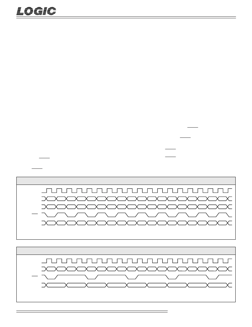
If one channel of non-interleaved video
(i.e., Luma) and one channel of inter-
leaved video (i.e., Chroma) is desired (see
Figure 6), non-interleaved video will be
driven to the output port W
12-0
and
interleaved video will be driven to the
output port X
12-0
with a delay of 2 CLK
cycles. For this operation, bit 2 must be set
to 0 and bit 3 must be set to 1 in Configu-
ration Register 0 (see Table 5).
If 4:2:2 interleaved video on one port is
desired (see Figure 7), interleaved video
will be driven to the output port W
12-0
with a delay of 4 CLK cycles. For this
operation, bit 2 must be set to 1 and bit 3
must be set to 0 in Configuration Register 0
(see Table 5).
All output multiplexing operations are
initiated by the latched HIGH to LOW
transitions of SYNC which synchronizes
the multiplexed output data to the LF3370
core (see SYNC discussion).
SYNC
SYNC control signal is required to
properly synchronize the input
demultiplexer, output multiplexer, and
F
IGURE
6. O
UTPUTTING
4:2:2:4 (I
NTERLEAVED
C
HROMA
ON
C
HANNEL
X)
CLK
There will be a HIGH to LOW transition on every Cb sample
W
12-0
Y
0
Y
1
Y
2
Y
3
Y
4
Y
5
Y
6
Y
7
Y
8
Y
9
Y
0 (Output SYNC)*
Y
10
Y
11
Y
12
*
Z
12-0
Y
13
Y
14
Y
15
Y
16
Y
17
CB
0
CR
0
CB
2
CR
2
CB
4
CR
4
CB
6
CR
6
CB
8
CR
8
CB
10
CR
10
CB
12
CR
12
CB
14
CR
14
CB
16
CR
16
K
0
K
1
K
2
K
3
K
4
K
5
K
6
K
7
K
8
K
9
K
10
K
11
K
12
K
13
K
14
K
15
K
16
K
17
X
12-0
F
IGURE
7. O
UTPUTTING
4:2:2:4 (I
NTERLEAVED
L
UMA
/C
HROMA
ON
C
HANNEL
W)
CLK
There will be a HIGH to LOW transition on every Cb sample
W
12-0
CB
0
Y
0
CR
0
Y
1
CB
2
Y
2
CR
2
Y
3
CB
4
Y
4
Y
0 (Output SYNC)*
CR
4
Y
5
CB
6
*
Z
12-0
Y
6
CR
6
Y
7
CR
8
Y
8
K
0
K
1
K
2
K
3
K
4
K
5
K
6
K
7
K
8
相關(guān)PDF資料 |
PDF描述 |
|---|---|
| LF3370 | High-Definition Video Format Converter(高清晰度視頻格式轉(zhuǎn)換器) |
| LF39J8 | DIODE ZENER TRIPLE ISOLATED 200mW 8.2Vz 20mA-Izt 0.05 3uA-Ir 6.5 SOT-363 3K/REEL |
| LF43881JC40 | 8 x 8-bit Digital Filter |
| LF43881 | 8 x 8-bit Digital Filter |
| LF48212QC20 | 12 x 12-bit Alpha Mixer |
相關(guān)代理商/技術(shù)參數(shù) |
參數(shù)描述 |
|---|---|
| LF33AB | 制造商:STMICROELECTRONICS 制造商全稱:STMicroelectronics 功能描述:Very low drop voltage regulators with inhibit |
| LF33ABDT | 功能描述:低壓差穩(wěn)壓器 - LDO 3.3V 0.5A Positive RoHS:否 制造商:Texas Instruments 最大輸入電壓:36 V 輸出電壓:1.4 V to 20.5 V 回動(dòng)電壓(最大值):307 mV 輸出電流:1 A 負(fù)載調(diào)節(jié):0.3 % 輸出端數(shù)量: 輸出類型:Fixed 最大工作溫度:+ 125 C 安裝風(fēng)格:SMD/SMT 封裝 / 箱體:VQFN-20 |
| LF33ABDT-TR | 功能描述:低壓差穩(wěn)壓器 - LDO 3.3V 0.5A Positive RoHS:否 制造商:Texas Instruments 最大輸入電壓:36 V 輸出電壓:1.4 V to 20.5 V 回動(dòng)電壓(最大值):307 mV 輸出電流:1 A 負(fù)載調(diào)節(jié):0.3 % 輸出端數(shù)量: 輸出類型:Fixed 最大工作溫度:+ 125 C 安裝風(fēng)格:SMD/SMT 封裝 / 箱體:VQFN-20 |
| LF33ABP | 功能描述:低壓差穩(wěn)壓器 - LDO 3.3V 0.5A Positive RoHS:否 制造商:Texas Instruments 最大輸入電壓:36 V 輸出電壓:1.4 V to 20.5 V 回動(dòng)電壓(最大值):307 mV 輸出電流:1 A 負(fù)載調(diào)節(jié):0.3 % 輸出端數(shù)量: 輸出類型:Fixed 最大工作溫度:+ 125 C 安裝風(fēng)格:SMD/SMT 封裝 / 箱體:VQFN-20 |
| LF33ABPT | 功能描述:低壓差穩(wěn)壓器 - LDO 3.3V 0.5A Positive RoHS:否 制造商:Texas Instruments 最大輸入電壓:36 V 輸出電壓:1.4 V to 20.5 V 回動(dòng)電壓(最大值):307 mV 輸出電流:1 A 負(fù)載調(diào)節(jié):0.3 % 輸出端數(shù)量: 輸出類型:Fixed 最大工作溫度:+ 125 C 安裝風(fēng)格:SMD/SMT 封裝 / 箱體:VQFN-20 |
發(fā)布緊急采購,3分鐘左右您將得到回復(fù)。