- 您現(xiàn)在的位置:買賣IC網(wǎng) > PDF目錄383236 > L6280 (意法半導(dǎo)體) THREE CHANNELS MULTIPOWER DRIVER SYSTEM PDF資料下載
參數(shù)資料
| 型號(hào): | L6280 |
| 廠商: | 意法半導(dǎo)體 |
| 英文描述: | THREE CHANNELS MULTIPOWER DRIVER SYSTEM |
| 中文描述: | 三通道移動(dòng)電站驅(qū)動(dòng)系統(tǒng) |
| 文件頁數(shù): | 17/26頁 |
| 文件大小: | 388K |
| 代理商: | L6280 |
第1頁第2頁第3頁第4頁第5頁第6頁第7頁第8頁第9頁第10頁第11頁第12頁第13頁第14頁第15頁第16頁當(dāng)前第17頁第18頁第19頁第20頁第21頁第22頁第23頁第24頁第25頁第26頁
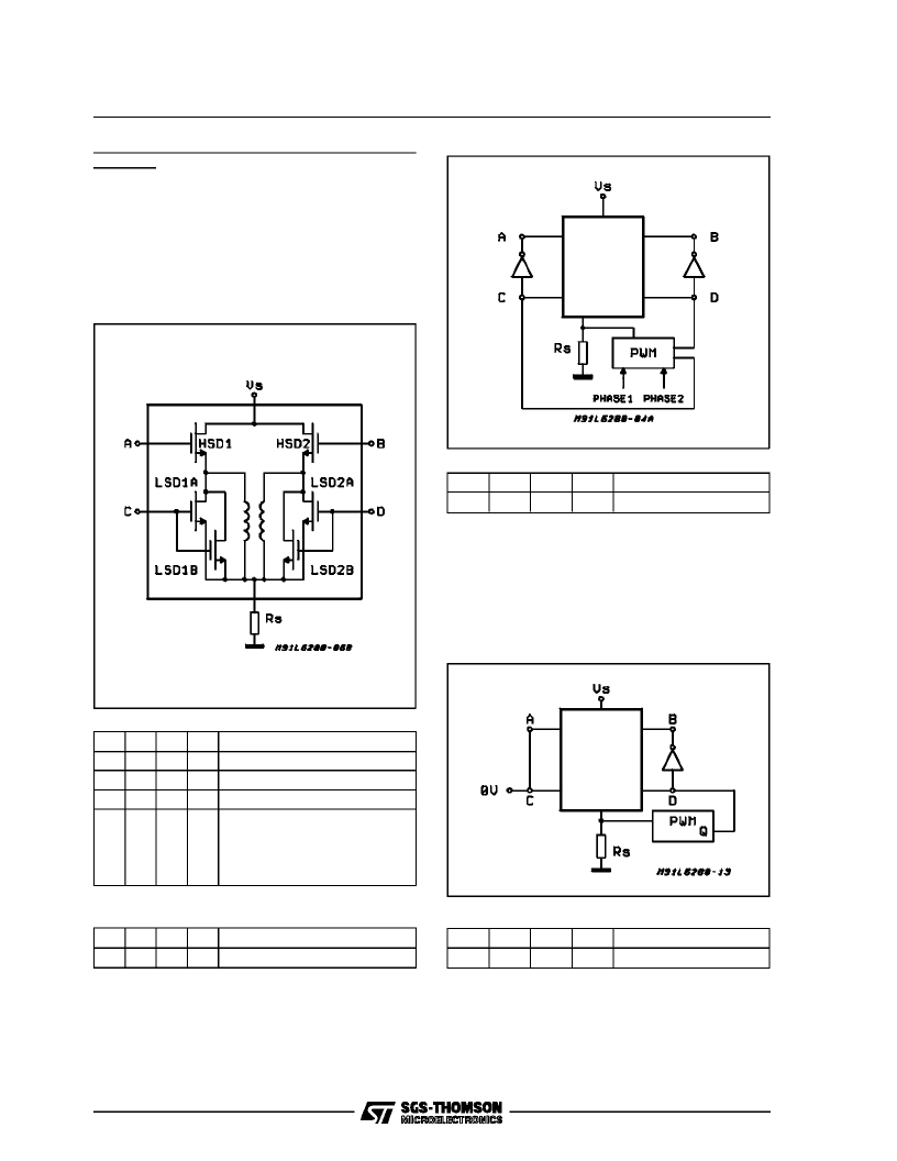
DUAL HALF BRIDGE CONFIGURATION (CH1
and CH2)
In dual half bridge configuration the connection
between the output of the high side drivers and
the corresponding low side drivers has to be
made with external jumpers. The output stage
block diagram shown in figure 20 must be substi-
tuted in side the blank boxes in the following
block diagrams. In dual half bridge configuration,
the time sharing strategy is always used.
Figure20
D0
X
X
X
D1
0
0
0
D2
0
0
1
D3
0
1
0
Tristate left and right
Chopper left, fixed righ
Chopper right, fixed left
Fixed left and right. For these
configurations, see the
corresponding shown in Full
Bridge Configuration paragraph
(Page 14/24).
X
0
1
1
D0
X
D1
1
D2
0
D3
0
Chopper left chopper right
As foreseen when in unipolar motor configura-
tion(see Figure 5), the time sharing strategy is
used (see Figure 10), so when the current in left
winding is controlled, the current in right winding
recirculate trough the low side drivers and not
throughthe sense resistor (Fig. 21).
Figure 21
D0
X
D1
1
D2
0
D3
1
Tristate left, chopperright
During ON time (Q = LOW) the current flows
through high side driver HSD2, right winding and
sense resistor. During OFF time the current recir-
culate through winding and side drivers LSD2A
and LSD2B (Fig. 22).
Figure 22
D0
X
D1
1
D2
1
D3
0
Tristate right, chopper left
During ON time (Q = LOW) the current flows
through high side driver HSD1, left winding and
sense resistor. During OFF time the current recir-
culate through the winding and low side drivers
LSD1A and LSD2A(Fig 23).
L6280
17/26
相關(guān)PDF資料 |
PDF描述 |
|---|---|
| L6285 | 3 CHANNELS MULTIPOWER SYSTEM |
| L6285S | 3 CHANNELS MULTIPOWER SYSTEM |
| L6316 | 4-CHANNEL LOW POWER PREAMPLIFIER |
| L634 | THREE PHASE MOTOR DRIVER |
| L6353 | Smart Driver for Power MOS & IGBT(用于MOS和絕緣柵雙極晶體管的智能驅(qū)動(dòng)器) |
相關(guān)代理商/技術(shù)參數(shù) |
參數(shù)描述 |
|---|---|
| L6281B12D | 制造商:ST MICRO 功能描述:New |
| L6282-3.2E | 制造商:STMicroelectronics 功能描述:L6282-3.2E |
| L6283-1.2 | 制造商:STMicroelectronics 功能描述:ELECTRONIC COMPONENT |
| L6283-1.3 | 制造商:STMicroelectronics 功能描述:ELECTRONIC COMPONENT |
| L6285 | 制造商:STMICROELECTRONICS 制造商全稱:STMicroelectronics 功能描述:3 CHANNELS MULTIPOWER SYSTEM |
發(fā)布緊急采購,3分鐘左右您將得到回復(fù)。