- 您現(xiàn)在的位置:買賣IC網(wǎng) > PDF目錄223858 > GMZAN3L (Electronic Theatre Controls, Inc.) XGA ALALOG INTERFACE LCD MONITOR CONTROLLER PDF資料下載
參數(shù)資料
| 型號: | GMZAN3L |
| 廠商: | Electronic Theatre Controls, Inc. |
| 英文描述: | XGA ALALOG INTERFACE LCD MONITOR CONTROLLER |
| 中文描述: | ALALOG的XGA液晶顯示器接口控制器 |
| 文件頁數(shù): | 6/53頁 |
| 文件大小: | 556K |
| 代理商: | GMZAN3L |
第1頁第2頁第3頁第4頁第5頁當(dāng)前第6頁第7頁第8頁第9頁第10頁第11頁第12頁第13頁第14頁第15頁第16頁第17頁第18頁第19頁第20頁第21頁第22頁第23頁第24頁第25頁第26頁第27頁第28頁第29頁第30頁第31頁第32頁第33頁第34頁第35頁第36頁第37頁第38頁第39頁第40頁第41頁第42頁第43頁第44頁第45頁第46頁第47頁第48頁第49頁第50頁第51頁第52頁第53頁
gmZAN3 Preliminary Data Sheet
C0523-DAT-01G
14
July 2003
Ge nes i s Microc hip Confid e n tia l
http:// w ww . g enesis-mic r ochip.com
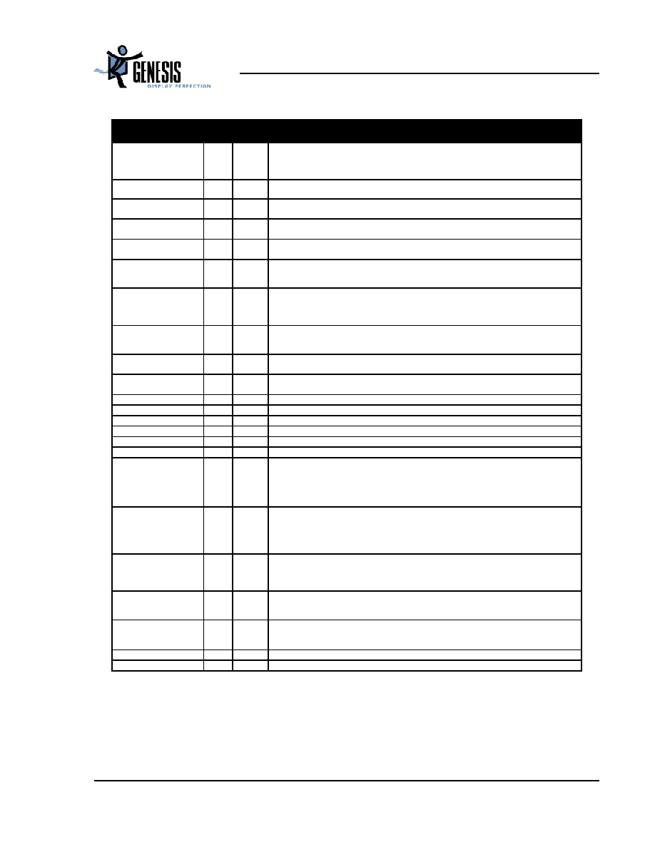
Table 4.
System Interface and GPIO Signals (gmZAN3L)
Pin Name
No
I/O
Description
RESETn
1
IO
Active-low hardware reset signal. The reset signal is held low for at least 150ms on the
chip power up. It has an internal 60Kl pull-up resistor which can be used for re-setting
other system devices. See section 4.2
[Bi-directional (open drain), 5V-tolerant]
RESET_OUT
2
O
Active-high hardware reset signal. The reset signal is held high for at least 150ms on the
chip power up. It can be used for re-setting other system devices[Output, 5V-tolerant]
GPIO0/PWM0
80
IO
General-purpose input/output signal or PWM0. Open drain option via register setting.
[Bi-directional, Schmitt trigger (400mV typical hysteresis), 5V-tolerant]
GPIO1/PWM1
79
IO
General-purpose input/output signal or PWM1. Open drain option via register setting.
[Bi-directional, Schmitt trigger (400mV typical hysteresis), 5V-tolerant]
GPIO2
78
IO
General-purpose input/output signal. Open drain option via register setting.
[Bi-directional, Schmitt trigger (400mV typical hysteresis), 5V-tolerant]
GPIO3/IRQn
116
IO
General-purpose input/output signal. This is also active-low interrupt input external micro-
controller.
[Bi-directional, Active low open drain, 5V-tolerant]
GPIO4/MEM_REG
117
IO-PD
General-purpose input/output signal. Open drain option via register setting. For 8-bit A/D
host interface, this selects between OSD memory (high) and register access (low).
[Bi-directional, Schmitt trigger (400mV typical hysteresis), 5V-tolerant, internal 60K pull-
down]
GPIO5/AD7
121
IO
General-purpose input/output signal or Adddress/data[7] for 8-bit A/D host interface. Open
drain option via register setting.
[Bi-directional, Schmitt trigger (400mV typical hysteresis), 5V-tolerant]
GPIO6/AD6
122
IO
General-purpose input/output signal or Adddress/data[6] for 8-bit A/D host interface.
[Bi-directional, Schmitt trigger (400mV typical hysteresis), 5V-tolerant]
GPIO7/AD5
123
IO
General-purpose input/output signal or Adddress/data[5] for 8-bit A/D host interface.
[Bi-directional, Schmitt trigger (400mV typical hysteresis), 5V-tolerant]
GPO8
60
O
General-purpose output signal.
GPO9
63
O
General-purpose output signal.
GPO10
52
O
General-purpose output.
GPO11
53
O
General-purpose output signal.
GPO12
40
O
General-purpose output signal.
GPO13
43
O
General-purpose output signal.
HDATA0/ADO/HP0
HDATA1/AD1/HP1
128
127
IO-PD
Host data for 6-wire serial protocol.
For 8-bit A/D host interface determines AD0 and AD1 bit.
Note: See Table 19, Boostrap Signals
[Bi-directional, Schmitt trigger (400mV typical hysteresis), 5V-tolerant, internal 60K pull-
down]
HDATA2/AD2/OSC_SEL
126
IO-PD
If using 6-wire protocol the HDATA[2] determines bit 2 of the host data. For 8-bit A/D host
interface determines AD2 bit.
Note: See Table 19, Boostrap Signals
[Bi-directional, Schmitt trigger (400mV typical hysteresis), 5V-tolerant, internal 60K pull-
down]
HDATA3/AD3
125
IO-PD
If using 6-wire protocol the HDATA[3] determines the upper AD3 bits of the host data. For
8-bit A/D host interface determines address/data bit.
[Bi-directional, Schmitt trigger (400mV typical hysteresis), 5V-tolerant, internal 60K pull-
down]
HFS/AD4
124
IO
Host Frame Sync. Frames the packet on the serial channel 6-wire interface. For 8-bit A/D host
interface determines AD4 bit.
[Bi-directional, Schmitt trigger (400mV typical hysteresis), slew rate limited, 5V-tolerant]
HCLK/ALE
118
I
Clock signal input for the 6-wire interface and 2-wire modes.
For 8-bit A/D host interface it becomes the Address Latch Enable.
[Input, Schmitt trigger (400mV typical hysteresis), 5V-tolerant]
WRn
119
I-PU
For 8-bit A/D host interface write strobe input. Internal 60K pull-up.
RDn
120
I-PU
For 8-bit A/D host interface read strobe input. Internal 60K pull-up.
相關(guān)PDF資料 |
PDF描述 |
|---|---|
| GMZAN3T | XGA ALALOG INTERFACE LCD MONITOR CONTROLLER |
| GMZJ12CT/R | 12.05 V, 0.5 W, SILICON, UNIDIRECTIONAL VOLTAGE REGULATOR DIODE |
| GMZJ12C | 12.05 V, 0.5 W, SILICON, UNIDIRECTIONAL VOLTAGE REGULATOR DIODE |
| GMZJ13B | 12.88 V, 0.5 W, SILICON, UNIDIRECTIONAL VOLTAGE REGULATOR DIODE |
| GMZJ13C | 13.33 V, 0.5 W, SILICON, UNIDIRECTIONAL VOLTAGE REGULATOR DIODE |
相關(guān)代理商/技術(shù)參數(shù) |
參數(shù)描述 |
|---|---|
| GMZAN3SL-LF-BD | 制造商:STMicroelectronics 功能描述:VIDEO CHIP- PACKAGE - Trays |
| GMZAN3T | 制造商:未知廠家 制造商全稱:未知廠家 功能描述:XGA ALALOG INTERFACE LCD MONITOR CONTROLLER |
| GMZJ | 制造商:RECTRON 制造商全稱:Rectron Semiconductor 功能描述:Micro MELF ZENER DIODE 2.5% 500mW |
| GMZJ10 | 制造商:RECTRON 制造商全稱:Rectron Semiconductor 功能描述:Micro MELF ZENER DIODE 2.5% 500mW |
| GMZJ10A _R1 _10001 | 制造商:PanJit Touch Screens 功能描述: |
發(fā)布緊急采購,3分鐘左右您將得到回復(fù)。