- 您現(xiàn)在的位置:買賣IC網(wǎng) > PDF目錄377114 > FLEX8000 (Altera Corporation) PROGRAMMABLE LOGIC DEVICES FAMILY PDF資料下載
參數(shù)資料
| 型號: | FLEX8000 |
| 廠商: | Altera Corporation |
| 英文描述: | PROGRAMMABLE LOGIC DEVICES FAMILY |
| 中文描述: | 系列可編程邏輯元件 |
| 文件頁數(shù): | 10/61頁 |
| 文件大小: | 979K |
| 代理商: | FLEX8000 |
第1頁第2頁第3頁第4頁第5頁第6頁第7頁第8頁第9頁當(dāng)前第10頁第11頁第12頁第13頁第14頁第15頁第16頁第17頁第18頁第19頁第20頁第21頁第22頁第23頁第24頁第25頁第26頁第27頁第28頁第29頁第30頁第31頁第32頁第33頁第34頁第35頁第36頁第37頁第38頁第39頁第40頁第41頁第42頁第43頁第44頁第45頁第46頁第47頁第48頁第49頁第50頁第51頁第52頁第53頁第54頁第55頁第56頁第57頁第58頁第59頁第60頁第61頁
10
Altera Corporation
FLEX 8000 Programmable Logic Device Family Data Sheet
The MAX+PLUS II Compiler can create cascade chains automatically
during design processing; designers can also insert cascade chain logic
manually during design entry. Cascade chains longer than eight LEs are
automatically implemented by linking LABs together. The last LE of an
LAB cascades to the first LE in the next LAB in the row.
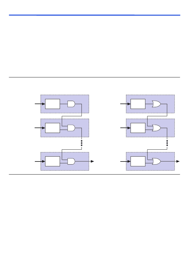
Figure 5
shows how the cascade function can connect adjacent LEs to
form functions with a wide fan-in. These examples show functions of 4
n
variables implemented with
n
LEs. For a device with an A-2 speed grade,
the LUT delay is approximately 1.6 ns; the cascade chain delay is 0.6 ns.
With the cascade chain, 4.2 ns is needed to decode a 16-bit address.
Figure 5. FLEX 8000 Cascade Chain Operation
LE Operating Modes
The FLEX 8000 LE can operate in one of four modes, each of which uses
LE resources differently. See
Figure 6
. In each mode, seven of the ten
available inputs to the LE—the four data inputs from the LAB local
interconnect, the feedback from the programmable register, and the
carry-in and cascade-in from the previous LE—are directed to different
destinations to implement the desired logic function. The three remaining
inputs to the LE provide clock, clear, and preset control for the register.
The MAX+PLUS II software automatically chooses the appropriate mode
for each application. Design performance can also be enhanced by
designing for the operating mode that supports the desired application.
d[3..0]
LE1
LUT
d[7..4]
LE2
LUT
d[(4n-1)..4(n-1)]
LEn
LUT
d[3..0]
LUT
d[7..4]
LUT
d[(4n-1)..4(n-1)]
LUT
LE1
LE2
LEn
AND Cascade Chain
OR Cascade Chain
相關(guān)PDF資料 |
PDF描述 |
|---|---|
| FLL120MK | L-Band Medium & High Power GaAs FET |
| FLL200IB-1 | L-Band Medium & High Power GaAs FET |
| FLL200IB-2 | L-Band Medium & High Power GaAs FET |
| FLL200IB-3 | L-Band Medium & High Power GaAs FET |
| FLL21E004ME | High Voltage - High Power GaAs FET |
相關(guān)代理商/技術(shù)參數(shù) |
參數(shù)描述 |
|---|---|
| FLEX8000_1 | 制造商:ALTERA 制造商全稱:Altera Corporation 功能描述:Programmable Logic Device Family |
| FLEXB-107/0.127 | 制造商:OKI Electric Cable 功能描述: |
| FLEXB-147/0.127 | 制造商:OKI Electric Cable 功能描述: |
| FLEXB-207/0.127 | 制造商:OKI Electric Cable 功能描述: |
| FLEX-B2100-7/0.1 | 制造商:YAMAICHI 制造商全稱:Yamaichi Electronics Co., Ltd. 功能描述:25MIL (0.635mm) OKIFLEX-B&S Type (150V, 105°C) |
發(fā)布緊急采購,3分鐘左右您將得到回復(fù)。