- 您現(xiàn)在的位置:買賣IC網(wǎng) > PDF目錄362657 > ELANSC300-33KC (ADVANCED MICRO DEVICES INC) Highly Integrated, Low-Power, 32-Bit Microcontroller PDF資料下載
參數(shù)資料
| 型號(hào): | ELANSC300-33KC |
| 廠商: | ADVANCED MICRO DEVICES INC |
| 元件分類: | 微控制器/微處理器 |
| 英文描述: | Highly Integrated, Low-Power, 32-Bit Microcontroller |
| 中文描述: | 32-BIT, 33 MHz, MICROCONTROLLER, PQFP208 |
| 封裝: | SHRINK, PLASTIC, QFP-208 |
| 文件頁(yè)數(shù): | 59/139頁(yè) |
| 文件大小: | 1388K |
| 代理商: | ELANSC300-33KC |
第1頁(yè)第2頁(yè)第3頁(yè)第4頁(yè)第5頁(yè)第6頁(yè)第7頁(yè)第8頁(yè)第9頁(yè)第10頁(yè)第11頁(yè)第12頁(yè)第13頁(yè)第14頁(yè)第15頁(yè)第16頁(yè)第17頁(yè)第18頁(yè)第19頁(yè)第20頁(yè)第21頁(yè)第22頁(yè)第23頁(yè)第24頁(yè)第25頁(yè)第26頁(yè)第27頁(yè)第28頁(yè)第29頁(yè)第30頁(yè)第31頁(yè)第32頁(yè)第33頁(yè)第34頁(yè)第35頁(yè)第36頁(yè)第37頁(yè)第38頁(yè)第39頁(yè)第40頁(yè)第41頁(yè)第42頁(yè)第43頁(yè)第44頁(yè)第45頁(yè)第46頁(yè)第47頁(yè)第48頁(yè)第49頁(yè)第50頁(yè)第51頁(yè)第52頁(yè)第53頁(yè)第54頁(yè)第55頁(yè)第56頁(yè)第57頁(yè)第58頁(yè)當(dāng)前第59頁(yè)第60頁(yè)第61頁(yè)第62頁(yè)第63頁(yè)第64頁(yè)第65頁(yè)第66頁(yè)第67頁(yè)第68頁(yè)第69頁(yè)第70頁(yè)第71頁(yè)第72頁(yè)第73頁(yè)第74頁(yè)第75頁(yè)第76頁(yè)第77頁(yè)第78頁(yè)第79頁(yè)第80頁(yè)第81頁(yè)第82頁(yè)第83頁(yè)第84頁(yè)第85頁(yè)第86頁(yè)第87頁(yè)第88頁(yè)第89頁(yè)第90頁(yè)第91頁(yè)第92頁(yè)第93頁(yè)第94頁(yè)第95頁(yè)第96頁(yè)第97頁(yè)第98頁(yè)第99頁(yè)第100頁(yè)第101頁(yè)第102頁(yè)第103頁(yè)第104頁(yè)第105頁(yè)第106頁(yè)第107頁(yè)第108頁(yè)第109頁(yè)第110頁(yè)第111頁(yè)第112頁(yè)第113頁(yè)第114頁(yè)第115頁(yè)第116頁(yè)第117頁(yè)第118頁(yè)第119頁(yè)第120頁(yè)第121頁(yè)第122頁(yè)第123頁(yè)第124頁(yè)第125頁(yè)第126頁(yè)第127頁(yè)第128頁(yè)第129頁(yè)第130頁(yè)第131頁(yè)第132頁(yè)第133頁(yè)第134頁(yè)第135頁(yè)第136頁(yè)第137頁(yè)第138頁(yè)第139頁(yè)
élanSC300 Microcontroller Data Sheet
59
P R E L I M I N A R Y
mode, as soon as VSYS is powered up, RSTDRV is im-
mediately driven High and will remain High until the
IORESET
signal is deasserted and the preserved pro-
grammed value in the PLL start-up timer has expired.
Force Term
Figure 4 on page 57 shows the schematic diagram,
and Table 24 shows the function of the IORESET,
RESIN, and Force Term. When in Micro Power Off
mode, it is important not to back power any of the pow-
ered-off internal power planes. Table 2
–Table 11 show
the VCCIO and VCC clamp voltage sources for each
signal pin. Ensure that all signals, which are either
driven by (VCCIO) or clamped to (VCC Clamp) a pow-
ered-off voltage source, are also either powered off or
driven Low.
PGP Pins
PGP2 and PGP3 can be programmed to be set to a
pre-defined state for Micro Power Off mode. For more
information, see the élan
TM
SC300 Microcontroller Pro-
grammer’s Reference Manual
, order # 18470.
Micro Power Off Mode Implementation
The system should not be powered up directly into
Micro Power Off mode. The system must be allowed to
fully power up into High Speed mode upon initial power
application of any power source. If a battery has insuf-
ficient power for the élanSC300 microcontroller to ini-
tialize into High Speed mode, the system design must
first power up the élanSC300 microcontroller from the
main source, and not allow the chip to be powered from
the battery until after it is fully initialized in High Speed
mode and properly transitioned into Micro Power Off
mode.
This requirement presents an issue when using (for ex-
ample) a 3-V Lithium battery cell as a back-up power
source to prevent the RTC from losing its contents dur-
ing Micro Power Off mode. If the battery is installed be-
fore any other power source is available, the
requirement cannot be met because such a small bat-
tery is incapable of supplying sufficient power to fully
initialize the system. The élanSC300 microcontroller
comes up in an undefined state, perhaps drawing suf-
ficient current to drain the battery.
The élanSC300 microcontroller backup power source
should be installed only after the system is powered by
the main power source prior to a transition into Micro
Power Off mode. When the system has transitioned
into Micro Power Off mode properly, the simultaneous
benefits of low power consumption while maintaining
RTC data such as time, date, and system configuration
can be realized.
Note:
The timing sequence and specifications for
power-up, entering, and exiting Micro Power Off mode
must be met. The timing specifications are shown in
Table 51 on page 99.
For more information, see the
élan
TM
SC300 and
élan
TM
SC310 Microcontrollers Solution For Systems
Using a Back-up Battery Application Note
, order
#20746 and the
Troubleshooting Guide for Micro
Power Off Mode on élan
TM
SC300 and élanSC310 Mi-
crocontrollers and Evaluation Boards Application Note
,
order #21810.
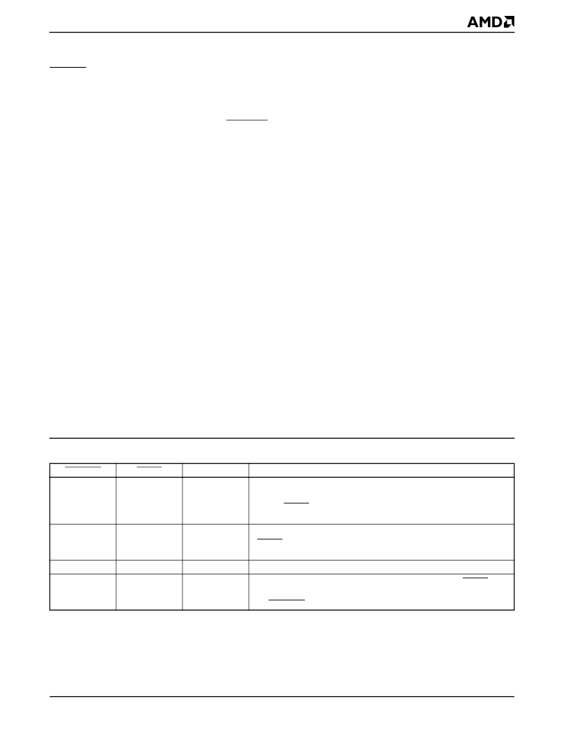
Table 24.
Internal I/O Pulldown States
IORESET
0
RESIN
0
Force Term
Active
Comments
This condition occurs when any power source is initially turned on. The
élanSC300 microcontroller’s core and analog VCC is transitioning to
on and RESIN is active (the initial power-up state). See the Micro Pow-
er Off Mode Implementation section below for more details.
This condition occurs when the core and analog VCC is stable, the
RESIN pin has been inactive, and the primary power supply outputs
are off (the normal Micro Power Off state).
This condition should be treated as condition 0,0 above.
This occurs when the secondary power supply is on, the RESIN
input is inactive, and the primary power supply is on and has deassert-
ed IORESET (normal system operating state).
0
1
Active
1
1
0
1
Active
Inactive
相關(guān)PDF資料 |
PDF描述 |
|---|---|
| ELANSC300-33KI | Highly Integrated, Low-Power, 32-Bit Microcontroller |
| ELANSC300-33VC | Highly Integrated, Low-Power, 32-Bit Microcontroller |
| ELANSC300 | Highly Integrated, Low-Power, 32-Bit Microcontroller |
| ELANSC300-25KC | Highly Integrated, Low-Power, 32-Bit Microcontroller |
| ELANSC300-25KI | Highly Integrated, Low-Power, 32-Bit Microcontroller |
相關(guān)代理商/技術(shù)參數(shù) |
參數(shù)描述 |
|---|---|
| ELANSC300-33KI | 制造商:AMD 制造商全稱:Advanced Micro Devices 功能描述:Highly Integrated, Low-Power, 32-Bit Microcontroller |
| ELANSC300-33VC | 制造商:Rochester Electronics LLC 功能描述:- Bulk 制造商:Advanced Micro Devices 功能描述: 制造商:AMD 功能描述: |
| ELANSC300-33VI | 制造商:AMD 制造商全稱:Advanced Micro Devices 功能描述:Highly Integrated, Low-Power, 32-Bit Microcontroller |
| ELANSC300WW WAF | 制造商:Advanced Micro Devices 功能描述: |
| ELANSC310 | 制造商:未知廠家 制造商全稱:未知廠家 功能描述:Elan SC310 - Elan SC310 Single-Chip. 32-Bit. PC/AT Microcontroller |
發(fā)布緊急采購(gòu),3分鐘左右您將得到回復(fù)。