- 您現(xiàn)在的位置:買賣IC網(wǎng) > PDF目錄17115 > EA-QSB-012 (Embedded Artists)BOARD QUICK START LPC1343 PDF資料下載
參數(shù)資料
| 型號(hào): | EA-QSB-012 |
| 廠商: | Embedded Artists |
| 文件頁數(shù): | 2/74頁 |
| 文件大小: | 0K |
| 描述: | BOARD QUICK START LPC1343 |
| 標(biāo)準(zhǔn)包裝: | 1 |
| 系列: | LPC13xx |
| 類型: | MCU |
| 適用于相關(guān)產(chǎn)品: | LPC1343 |
| 所含物品: | 板 |
第1頁當(dāng)前第2頁第3頁第4頁第5頁第6頁第7頁第8頁第9頁第10頁第11頁第12頁第13頁第14頁第15頁第16頁第17頁第18頁第19頁第20頁第21頁第22頁第23頁第24頁第25頁第26頁第27頁第28頁第29頁第30頁第31頁第32頁第33頁第34頁第35頁第36頁第37頁第38頁第39頁第40頁第41頁第42頁第43頁第44頁第45頁第46頁第47頁第48頁第49頁第50頁第51頁第52頁第53頁第54頁第55頁第56頁第57頁第58頁第59頁第60頁第61頁第62頁第63頁第64頁第65頁第66頁第67頁第68頁第69頁第70頁第71頁第72頁第73頁第74頁
LPC1311_13_42_43
All information provided in this document is subject to legal disclaimers.
NXP B.V. 2012. All rights reserved.
Product data sheet
Rev. 5 — 6 June 2012
10 of 74
NXP Semiconductors
LPC1311/13/42/43
32-bit ARM Cortex-M3 microcontroller
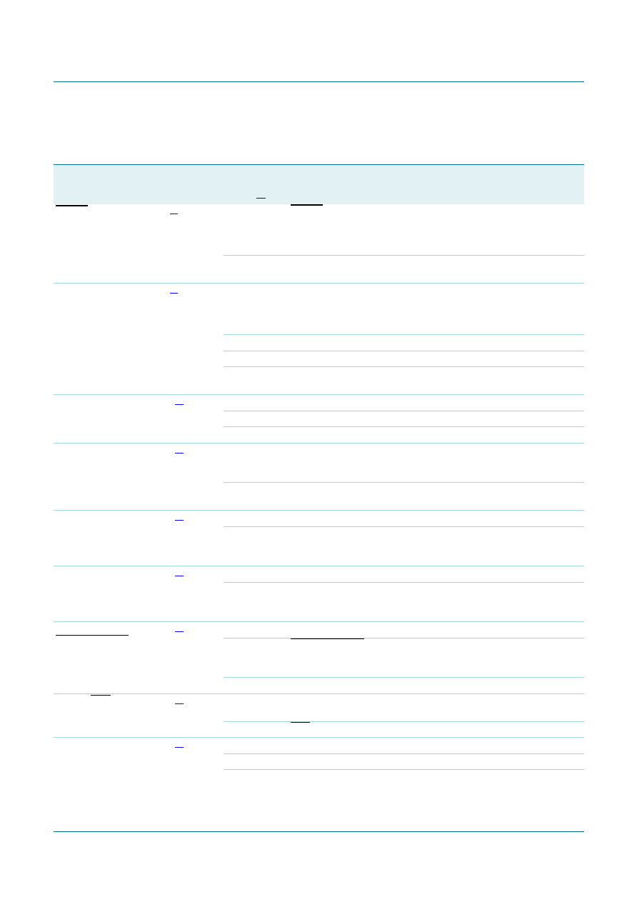
6.2 Pin description
Table 3.
LPC1313/42/43 LQFP48 pin description table
Symbol
Pin
Start
logic
input
Type Reset
state
Description
RESET/PIO0_0
3[2]
yes
I
I; PU
RESET — External reset input with 20 ns glitch filter. A LOW-going
pulse as short as 50 ns on this pin resets the device, causing I/O
ports and peripherals to take on their default states, and processor
execution to begin at address 0.
I/O
-
PIO0_0 — General purpose digital input/output pin with 10 ns glitch
filter.
PIO0_1/CLKOUT/
CT32B0_MAT2/
USB_FTOGGLE
4[3]
yes
I/O
I; PU
PIO0_1 — General purpose digital input/output pin. A LOW level on
this pin during reset starts the ISP command handler or the USB
device enumeration (USB on LPC1342/43 only, see description of
PIO0_3).
O-
CLKOUT — Clockout pin.
O-
CT32B0_MAT2 — Match output 2 for 32-bit timer 0.
O-
USB_FTOGGLE — USB 1 ms Start-of-Frame signal (LPC1342/43
only).
PIO0_2/SSEL0/
CT16B0_CAP0
10[3] yes
I/O
I; PU
PIO0_2 — General purpose digital input/output pin.
I/O
-
SSEL0 — Slave select for SSP0.
I-
CT16B0_CAP0 — Capture input 0 for 16-bit timer 0.
PIO0_3/USB_VBUS
14[3] yes
I/O
I; PU
PIO0_3 — General purpose digital input/output pin. LPC1342/43
only: A LOW level on this pin during reset starts the ISP command
handler, a HIGH level starts the USB device enumeration.
I-
USB_VBUS — Monitors the presence of USB bus power
(LPC1342/43 only).
PIO0_4/SCL
15[4] yes
I/O
I; IA
PIO0_4 — General purpose digital input/output pin (open-drain).
I/O
-
SCL — I2C-bus clock input/output (open-drain). High-current sink
only if I2C Fast-mode Plus is selected in the I/O configuration
register.
PIO0_5/SDA
16[4] yes
I/O
I; IA
PIO0_5 — General purpose digital input/output pin (open-drain).
I/O
-
SDA — I2C-bus data input/output (open-drain). High-current sink
only if I2C Fast-mode Plus is selected in the I/O configuration
register.
PIO0_6/
USB_CONNECT/
SCK0
22[3] yes
I/O
I; PU
PIO0_6 — General purpose digital input/output pin.
O-
USB_CONNECT — Signal used to switch an external 1.5 k
Ω
resistor under software control. Used with the SoftConnect USB
feature (LPC1342/43 only).
I/O
-
SCK0 — Serial clock for SSP0.
PIO0_7/CTS
23[3] yes
I/O
I; PU
PIO0_7 — General purpose digital input/output pin (high-current
output driver).
I-
CTS — Clear To Send input for UART.
PIO0_8/MISO0/
CT16B0_MAT0
27[3] yes
I/O
I; PU
PIO0_8 — General purpose digital input/output pin.
I/O
-
MISO0 — Master In Slave Out for SSP0.
O-
CT16B0_MAT0 — Match output 0 for 16-bit timer 0.
相關(guān)PDF資料 |
PDF描述 |
|---|---|
| EEM25DRYN-S13 | CONN EDGECARD 50POS .156 EXTEND |
| MAX8808XETA+TG104 | IC CHARGER LI+ SGLL CCCV 8TDFN |
| EEC18DREI-S734 | CONN EDGECARD 36POS .100 EYELET |
| EEC25DRES-S93 | CONN EDGECARD 50POS .100 EYELET |
| VE-JTF-EZ | CONVERTER MOD DC/DC 72V 25W |
相關(guān)代理商/技術(shù)參數(shù) |
參數(shù)描述 |
|---|---|
| EA-QSB-015 | 功能描述:開發(fā)板和工具包 - ARM QUICK START BOARD LPC11U35 RoHS:否 制造商:Arduino 產(chǎn)品:Development Boards 工具用于評(píng)估:ATSAM3X8EA-AU 核心:ARM Cortex M3 接口類型:DAC, ICSP, JTAG, UART, USB 工作電源電壓:3.3 V |
| EA-QSB-016 | 制造商:Embedded Artists 功能描述:BOARD QUICK START LPC4088 |
| EA-QSB-017 | 制造商:Embedded Artists 功能描述:BOARD QSB BASE LPC4088 |
| EA-QSB-100 | 功能描述:開發(fā)板和工具包 - ARM QUICKSTART PROTOTYPE BRD RoHS:否 制造商:Arduino 產(chǎn)品:Development Boards 工具用于評(píng)估:ATSAM3X8EA-AU 核心:ARM Cortex M3 接口類型:DAC, ICSP, JTAG, UART, USB 工作電源電壓:3.3 V |
| EA-QSB-102 | 功能描述:開發(fā)板和工具包 - ARM QUICKSTART PROTOTYPE BRD W/ LPC2106 RS232 RoHS:否 制造商:Arduino 產(chǎn)品:Development Boards 工具用于評(píng)估:ATSAM3X8EA-AU 核心:ARM Cortex M3 接口類型:DAC, ICSP, JTAG, UART, USB 工作電源電壓:3.3 V |
發(fā)布緊急采購(gòu),3分鐘左右您將得到回復(fù)。