- 您現(xiàn)在的位置:買賣IC網(wǎng) > PDF目錄377002 > DSPE56007FJ88 DSP|24-BIT|CMOS|QFP|80PIN|PLASTIC PDF資料下載
參數(shù)資料
| 型號: | DSPE56007FJ88 |
| 英文描述: | DSP|24-BIT|CMOS|QFP|80PIN|PLASTIC |
| 中文描述: | 數(shù)字信號處理器| 24位|的CMOS | QFP封裝| 80腳|塑料 |
| 文件頁數(shù): | 59/83頁 |
| 文件大小: | 382K |
| 代理商: | DSPE56007FJ88 |
第1頁第2頁第3頁第4頁第5頁第6頁第7頁第8頁第9頁第10頁第11頁第12頁第13頁第14頁第15頁第16頁第17頁第18頁第19頁第20頁第21頁第22頁第23頁第24頁第25頁第26頁第27頁第28頁第29頁第30頁第31頁第32頁第33頁第34頁第35頁第36頁第37頁第38頁第39頁第40頁第41頁第42頁第43頁第44頁第45頁第46頁第47頁第48頁第49頁第50頁第51頁第52頁第53頁第54頁第55頁第56頁第57頁第58頁當前第59頁第60頁第61頁第62頁第63頁第64頁第65頁第66頁第67頁第68頁第69頁第70頁第71頁第72頁第73頁第74頁第75頁第76頁第77頁第78頁第79頁第80頁第81頁第82頁第83頁
Specifications
Serial Host Interface (SHI) I
2
C Protocol Timing
MOTOROLA
DSP56007/D
2-35
Note:
1.
2.
C
L
is in pF, R
P
is in k
, and result is in ns.
A t
I
Bypassed Filter mode.
A t
I
Narrow Filter mode.
A t
I
Filter mode.
A t
I
Bypassed Filter mode.
A t
I
Narrow Filter mode.
A t
I
Filter mode.
A t
I
Bypassed Filter mode.
A t
I
Narrow Filter mode.
A t
I
Filter mode.
Refer to the
DSP56007 User’s Manual
for a detailed description of how to use the different filtering
modes.
2
CCP
of 34
×
T
C
(the maximum permitted for the given bus load) was used for the calculations in the
2
CCP
of 36
×
T
C
(the maximum permitted for the given bus load) was used for the calculations in the
2
CCP
of 40
×
T
C
(the maximum permitted for the given bus load) was used for the calculations in the Wide
3.
2
CCP
of 43
×
T
C
(the maximum permitted for the given bus load) was used for the calculations in the
2
CCP
of 46
×
T
C
(the maximum permitted for the given bus load) was used for the calculations in the
2
CCP
of 51
×
T
C
(the maximum permitted for the given bus load) was used for the calculations in the Wide
4.
2
CCP
of 56
×
T
C
(the maximum permitted for the given bus load) was used for the calculations in the
2
CCP
of 60
×
T
C
(the maximum permitted for the given bus load) was used for the calculations in the
2
CCP
of 66
×
T
C
(the maximum permitted for the given bus load) was used for the calculations in the Wide
5.
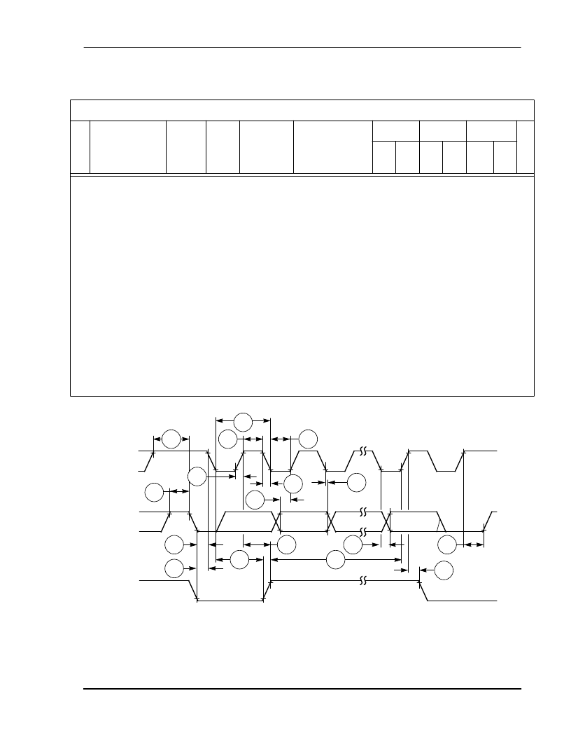
Figure 2-21
I
2
C Timing
Table 2-15
SHI Improved I
2
C Protocol Timing (Continued)
Improved I
2
C (C
L
= 50 pF, R
P
= 2 k
)
No.
Char.
Sym.
Mode
Filter
Mode
Expression
50 MHz
2
66 MHz
3
88 MHz
4
U
n
i
t
Min Max Min Max Min Max
Start
SCL
HREQ
SDA
ACK
MSB
LSB
Stop
171
Stop
173
176
175
177
178
180
179
172
186
182
183
189
174
188
184
187
AA0275
相關PDF資料 |
PDF描述 |
|---|---|
| DSPCOMMANDUM | Universal Command Converter for DSP User's Manual |
| DSPCOMMPARALLELUM | Parallel Port Command Converter for DSP User's Manual |
| DSPCOMMPCIUM | PCI Command Converter for DSP User's Manual |
| DSPG4001-71 | Telecommunication IC |
| DSPG5002 | Analog IC |
相關代理商/技術參數(shù) |
參數(shù)描述 |
|---|---|
| DSPF3-S7-120V | 制造商:Black Box Corporation 功能描述:DIGITAL SIGNAGE POWER FILTER |
| DSPF3-S7-120V-W1 | 制造商:Black Box Corporation 功能描述:1 YEAR WARRANTY FOR DSPF3-S7-120V |
| DSPF3-S7-120V-W3 | 制造商:Black Box Corporation 功能描述:3 YEAR WARRANTY FOR DSPF3-S7-120V |
| DSPF56362PV100 | 制造商:Rochester Electronics LLC 功能描述:- Bulk |
| DSPFPK52 | 制造商:BARRY CONTROLS/VLIER 功能描述: |
發(fā)布緊急采購,3分鐘左右您將得到回復。